Case Study — Basic Custom Block Library
Getting Started
This case study explains how to build your own library of custom blocks based on component files. It uses an example library of capacitor models. The library makes use of the Simscape™ Foundation electrical domain, and defines three simple components. For more advanced topics, including adding multiple levels of hierarchy, adding new domains, and customizing the appearance of a library, see Case Study — Electrochemical Library.
The example library comes built and on your path so that it is readily executable. However, it is recommended that you copy the source files to a new folder, for which you have write permission, and add that folder to your MATLAB® path. This will allow you to make changes and rebuild the library for yourself. The source files for the example library are in the following namespace folder:
matlabroot/toolbox/physmod/simscape/supporting_files/example_libraries/+Capacitors
where matlabroot is the MATLAB root folder on your machine, as returned by entering
matlabroot
in the MATLAB Command Window.
After copying the files, change the folder name +Capacitors to
another name, for example +MyCapacitors, so that your copy of the
library builds with a unique name.
Building the Custom Library
To build the library, type
sscbuild MyCapacitors
in the MATLAB Command Window. If building from within the
+MyCapacitors namespace folder, you can omit the argument and
type just
sscbuild
When the build completes, open the generated library by typing
MyCapacitors_lib
For more information on the library build process, see Building Custom Block Libraries.
Adding a Block
To add a block, write a corresponding component file and place it in the namespace
folder. For example, the Ideal Capacitor block in your
MyCapacitors_lib library is produced by the
IdealCapacitor.ssc file. Open this file in the MATLAB Editor and examine its contents.
component IdealCapacitor
% Ideal Capacitor
% Models an ideal (lossless) capacitor. The output current I is related
% to the input voltage V by I = C*dV/dt where C is the capacitance.

% Copyright 2008-2017 The MathWorks, Inc.

    nodes
        p = foundation.electrical.electrical; % +:top
        n = foundation.electrical.electrical; % -:bottom
    end

    parameters
        C = { 1, 'F' }; % Capacitance
    end

    variables
        i = { 0, 'A'   }; % Current
        v = {value = { 0, 'V' }, priority = priority.high}; % Voltage drop
    end

    branches
        i : p.i -> n.i; % Through variable i from node p to node n
    end

    equations
        assert(C > 0)
        v == p.v-n.v; % Across variable v from p to n
        i == C*der(v); % Capacitor equation
    end

end
First, let us examine the elements of the component file that affect the block
appearance. Double-click the Ideal Capacitor block in the
MyCapacitors_lib library to open its dialog box, and compare
the block icon and dialog box to the contents of the
IdealCapacitor.ssc file. The block name, Ideal Capacitor, is
taken from the comment on line 2. The comments on lines 3 and 4 are then taken to
populate the block description in the dialog box. The block ports are defined by the
nodes section. The comment expressions at the end of each line control the port
label and location. Similarly in the parameters section, the comments are used to
define parameter names in the block dialog box. For details, see Customizing the Block Name and Appearance.
Also notice that in the equation section there is an assert to ensure that the capacitance value is always greater than zero. This is good practice to ensure that a component is not used outside of its domain of validity. The Simscape Foundation library blocks have such checks implemented where appropriate.
Adding Detail to a Component
In this example library there are two additional components that can be used for ultracapacitor modeling. These components are evolutions of the Ideal Capacitor. It is good practice to incrementally build component models, adding and testing additional features as they are added.
Ideal Ultracapacitor
Ultracapacitors, as their name suggests, are capacitors with a very high capacitance value. The relationship between voltage and charge is not constant, unlike for an ideal capacitor. Suppose a manufacturer data sheet gives a graph of capacitance as a function of voltage, and that capacitance increases approximately linearly with voltage from the 1 farad at zero volts to 1.5 farads when the voltage is 2.5 volts. If the capacitance voltage is denoted v, then the capacitance can be approximated as:
For a capacitor, current i and voltage v are related by the standard equation
and hence
where C0 = 1 and
Cv = 0.2. This equation is
implemented by the following line in the equation section of the Simscape file IdealUltraCapacitor.ssc:
i == (C0 + Cv*v)*der(v);In order for the Simscape software to interpret this equation, the variables
(v and i) and the parameters
(C0 and Cv) must be defined in the
declaration section. For more information, see Declare Component Variables and
Declare Component Parameters.
Adding a Component with an Internal Variable
Implementing some component equations requires the use of internal variables. An example is when implementing an ultracapacitor with resistive losses. There are two resistive terms, the effective series resistance R, and the self-discharge resistance Rd. Because of the topology, it is not possible to directly express the capacitor equations in terms of the through and across variables i and v.
Ultracapacitor with Resistive Losses
This block is implemented by the component file
LossyUltraCapacitor.ssc. Open this file in the MATLAB Editor and examine its contents.
component LossyUltraCapacitor
% Lossy Ultracapacitor
% Models an ultracapacitor with resistive losses. The capacitance C
% depends on the voltage V according to C = C0 + V*dC/dV. A
% self-discharge resistance is included in parallel with the capacitor,
% and an equivalent series resistance in series with the capacitor.

% Copyright 2008-2017 The MathWorks, Inc.

    nodes
        p = foundation.electrical.electrical; % +:top
        n = foundation.electrical.electrical; % -:bottom
    end

    parameters
        C0 = { 1, 'F' };    % Nominal capacitance C0 at V=0
        Cv = { 0.2, 'F/V'}; % Rate of change of C with voltage V
        R = {2, 'Ohm' };    % Effective series resistance
        Rd = {500, 'Ohm' }; % Self-discharge resistance
    end

    variables
        i = { 0, 'A'   }; % Current
        vc = {value = { 0, 'V' }, priority = priority.high}; % Capacitor voltage
    end

    branches
        i : p.i -> n.i; % Through variable i from node p to node n
    end

    equations
        assert(C0 > 0)
        assert(R > 0)
        assert(Rd > 0)
        let
            v = p.v-n.v; % Across variable v from p to n
        in
            i == (C0 + Cv*vc)*der(vc) + vc/Rd; % Equation 1
            v == vc + i*R;                    % Equation 2
        end
    end

end
The additional variable is used to denote the voltage across the capacitor, vc. The equations can then be expressed in terms of v, i, and vc using Kirchhoff’s current and voltage laws. Summing currents at the capacitor + node gives the first Simscape equation:
i == (C0 + Cv*vc)*der(vc) + vc/Rd;Summing voltages gives the second Simscape equation:
v == vc + i*R;As a check, the number of equations required for a component used in a single connected network is given by the sum of the number of ports plus the number of internal variables minus one. This is not necessarily true for all components (for example, one exception is mass), but in general it is a good rule of thumb. Here this gives 2 + 1 - 1 = 2.
In the Simscape file, the initial condition (initial voltage in this example) is
applied to variable vc with priority =
priority.high, because this is a differential variable. In this case,
vc is readily identifiable as the differential variable as it
has the der (differentiator) operator applied to it.
Customizing the Block Icon
The capacitor blocks in the example library MyCapacitors_lib
have icons associated with them.
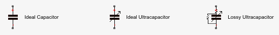
During the library build, if there is an image file in the folder with the same
name as the Simscape component file, then this is used to define the icon for the block.
For example, the Ideal Capacitor block defined by
IdealCapacitor.ssc uses the
IdealCapacitor.jpg to define its block icon. If you do not
include an image file, then the block displays its name in place of an icon. For
details, see Customize the Block Icon.