Build Detailed Model of Battery Pack from Pouch Cells
This example shows how to create and build Simscape™ system models for various battery designs and configurations based on pouch battery cells in Simscape Battery™. The buildBattery function allows you to automatically generate Simscape models for these Simscape Battery objects:
This function creates a library in your working folder that contains a system model block of a battery pack. You can use this system model as a reference in your simulations. The run-time parameters for these models, such as the battery cell impedance or the battery open-circuit voltage, are defined after the model creation and are therefore not covered by the Battery Pack Builder classes. To define the run-time parameters, you can either specify them in the block mask of the generated Simscape models or use the MaskParameters argument of the buildBattery function.
During the first half of this example, you first define the key properties of a pouch battery cell and block model. You then use this pouch battery cell as a fundamental repeating unit inside a parallel assembly component. In the industry this component is also called a "sub-module", a "super-cell", a "P-set", or just a "cell". You later employ this parallel assembly to define a battery module, which is then used to create a module assembly and finally a battery pack. These larger battery systems all use the battery cell as a fundamental repeating unit. Throughout the workflow, you visualize the geometry and the relative positioning of these battery systems by using the BatteryChart object.
In the second half of the example, you modify the modeling methodology and the model resolution of the Module, ModuleAssemblies, and Pack objects before generating the final Simscape battery model. You can perform the geometrical aggregation or stacking of any battery object along the sequence either along the X or Y axis. These axis mirror the Coordinate Systems in Vehicle Dynamics Blockset (Vehicle Dynamics Blockset).
Create and Visualize Battery Objects in MATLAB
To create a battery pack, you must first design and create the foundational elements of the battery pack.
This figure shows the overall process to create a battery pack object in a bottom-up approach:

A battery pack comprises multiple module assemblies. These module assemblies, in turn, comprise a number of battery modules connected electrically in series or in parallel. The battery modules are made of multiple parallel assemblies which, in turn, comprise a number of battery cells connected electrically in parallel under a specific topological configuration or geometrical arrangement.
Create and Visualize Battery Cell Object
A battery cell is an electrochemical energy storage device that provides electrical energy from stored chemical energy. An electrochemical battery cell is the fundamental building block in the manufacturing of larger battery systems. To obtain the required energy and voltage levels, multiple battery cells are typically connected electrically in parallel and/or in series.
To mirror the real-world behavior, the Simscape Battery Cell object is the foundational element for the creation of a battery pack system model. You can create all battery classes without any inputs. To create a battery cell, use the batteryCell function.
foundationCell = batteryCell();
To meet the battery packaging and space requirements, you can arrange the battery cells in three main geometrical arrangements: cylindrical, pouch, or prismatic. To visualize a single battery cell, you must first define its geometry.
Define a pouch geometry by using the batteryPouchGeometry function.
cellGeometry = batteryPouchGeometry();
The PouchGeometry object has six properties:
Length— Length of the pouch geometry, specified as asimscape.Valueobject that represents a scalar with a unit of length.Thickness— Thickness of the pouch geometry, specified as asimscape.Valueobject that represents a scalar with a unit of length.Height— Height of the pouch geometry, specified as asimscape.Valueobject that represents a scalar with a unit of length.TabLocation— Location of the tabs of a pouch battery cell, specified as eitherStandardorOpposed.TabWidth— Width of the tab of a pouch battery cell, specified as asimscape.Valueobject that represents a scalar with a unit of length.TabHeight— Height of the tab of a pouch battery cell, specified as asimscape.Valueobject that represents a scalar with a unit of length.
Specify custom values for the Length, Height, TabWidth, and TabLocation properties of the pouch geometry.
cellGeometry.Length = simscape.Value(0.36,"m");
cellGeometry.Height = simscape.Value(0.13,"m");
cellGeometry.TabWidth = simscape.Value(0.05,"m");
cellGeometry.TabLocation = "Opposed";
For more information on the possible geometrical arrangements of a battery cell, see the CylindricalGeometry and PrismaticGeometry documentation pages.
You can now link this geometry object to the battery cell by accessing the Geometry property of the foundationCell object.
foundationCell.Geometry = cellGeometry;
Specify a custom value for the mass of the battery cell by using the Mass property.
foundationCell.Mass = simscape.Value(0.8,"kg");
disp(foundationCell)
Cell with properties:
Geometry: [1×1 simscape.battery.builder.PouchGeometry]
CellModelOptions: [1×1 simscape.battery.builder.CellModelBlock]
Mass: 0.8000 (kg)
Capacity: 5 (A*hr)
Energy: 50 (W*hr)
Show all properties
To visualize the battery cell before you build the system model and to view its model resolution, create the figure where you want to visualize your cell and then use the batteryChart function.
f = figure("Color", "white");
cellChart = batteryChart(f,foundationCell);
title(cellChart,"Pouch Cell")

By default, the Battery Equivalent Circuit block is the electrical and thermal model used to represent and simulate this battery cell in Simscape. When scaled up into larger battery systems like a parallel assembly or a module, this model is also scaled up accordingly depending on the model resolution. To display the information about the cell model block, use the CellModelOptions property of the batterycell object.
disp(foundationCell.CellModelOptions.CellModelBlockPath);
batt_lib/Cells/Battery Equivalent Circuit
The Cell object also allows you to simulate the thermal effects of the battery cell by using a simple 1-D model. To simulate the thermal effects of the battery cell, in the BlockParameters property of the CellModelOptions property of the Cell object, set the ThermalModel parameter to "LumpedThermalMass".
foundationCell.CellModelOptions.BlockParameters.ThermalModel = "LumpedThermalMass";You can modify all the conditional parameters of the Battery Equivalent Circuit block by using the CellModelOptions property.
disp(foundationCell.CellModelOptions.BlockParameters);
        CurrentDependence: Disabled
    SelfDischargeResistor: Disabled
                  RCPairs: noDynamics
       CyclingAgingMethod: disabled
    CalendarAgeResistance: Disabled
      CalendarAgeCapacity: Disabled
             ThermalModel: LumpedThermalMass
          HysteresisModel: none
      ReversibleHeatModel: Disabled
      CalendarAgingMethod: equation
          StorageVariable: OCV
Create and Visualize Battery ParallelAssembly Object
A battery parallel assembly comprises multiple battery cells connected electrically in parallel under a specific topological configuration or geometrical arrangement. You can specify the number of cells connected in parallel by using the NumParallelCells property.
In this example, you create a parallel assembly using four pouch cells, stacked in a single stack topology with a gap between the cells equal to 0.001 meters.
parallelAssembly = batteryParallelAssembly(foundationCell,...
    4,Topology="SingleStack", ...
    InterCellGap=simscape.Value(0.001,"m"));
The Topology property is a function of the cell format. For pouch cells, the only available topology is "SingleStack". By default, the ParallelAssembly object stacks the cells along the Y axis.
Visualize the battery parallel assembly. Create the figure where you want to visualize your battery parallel assembly and use the batteryChart function.
f = figure("Color","white");
parallelAssemblyChart = batteryChart(f,parallelAssembly);
title(parallelAssemblyChart,"Parallel Assembly Chart")

You can modify all the public properties inside the parallel assembly after its creation.
You can check the cell packaging volume and the mass of any battery by accessing the PackagingVolume and CumulativeMass properties.
disp(parallelAssembly.PackagingVolume)
0.0023 (m^3)
disp(parallelAssembly.CumulativeMass)
3.2000 (kg)
Create and Visualize Battery Module Object
A battery module comprises multiple parallel assemblies connected in series. You can specify the number of parallel assemblies connected in series by using the NumSeriesAssemblies property. You can stack or geometrically assemble batteries along the X or Y axis of a Cartesian coordinate system by using the StackingAxis property.
In this example, you create a battery module using 14 parallel assemblies with an intergap between each assembly equal to 0.008 meters.
module = batteryModule(...
    parallelAssembly,14, ...
    InterParallelAssemblyGap=simscape.Value(0.008,"m"));
Visualize the battery Module object. Create the figure where you want to visualize your battery module and use the batteryChart function.
f = figure("Color","white");
moduleChart = batteryChart(f,module);
title(moduleChart,"Module Chart")
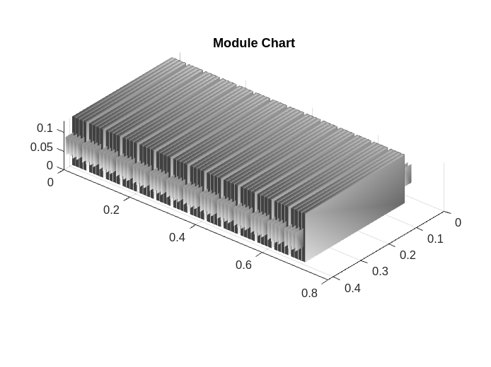
Display the total packaging volume and cumulative mass of your battery module.
disp(module.PackagingVolume)
0.0385 (m^3)
disp(module.CumulativeMass)
44.8000 (kg)
You can modify all the public properties inside the module after its creation.
Create and Visualize Battery ModuleAssembly Object
A battery module assembly comprises multiple battery modules connected in series or in parallel. You can define the number and types of modules by using the Module property. If a module assembly comprises many identical modules, use the repmat function. Otherwise use an array of distinct modules.
In this example, you create a battery module assembly by using two identical Module objects, with an intergap between each module equal to 0.1 meters. By default, the ModuleAssembly object electrically connects the modules in series.
moduleAssembly = batteryModuleAssembly(...
    repmat(module,1,2), ...
    InterModuleGap=simscape.Value(0.1,"m"));
Visualize the battery ModuleAssembly object. Create the figure where you want to visualize your battery module assembly and use the batteryChart function.
f = figure("Color","white");
moduleChart = batteryChart(f,moduleAssembly);
title(moduleChart,"Module Assembly Chart")

All battery objects, including modules, have a Name property. The ModuleAssembly object automatically assigns a unique name to all of its modules. To display the name of each module in your ModuleAssembly object, use the Name property.
disp(moduleAssembly.Module(1).Name);
Module1
disp(moduleAssembly.Module(2).Name);
Module2
You can modify the Name property to rename any of the modules inside a module assembly. Specify a new name for the two modules in your battery module assembly.
moduleAssembly.Module(1).Name = "MyModuleA";
moduleAssembly.Module(2).Name = "MyModuleB";
disp(moduleAssembly.Module(1).Name);
MyModuleA
disp(moduleAssembly.Module(2).Name);
MyModuleB
A ModuleAssembly battery object also allows you to stack the modules along the Z axis. To stack modules along the Z axis, use the NumLevels property. The NumLevels property defines the number of levels, tiers, or floors of the module assembly. The ModuleAssembly object stacks the modules symmetrically according to the number of levels and modules in the assembly.
For example, create a new ModuleAssembly object that comprises four identical modules stacked along the Z axis on two levels.
zStackedModuleAssembly = batteryModuleAssembly(...
    repmat(module,1,4), ...
    NumLevel=2,...
    InterModuleGap=simscape.Value(0.1,"m"));
Visualize the ModuleAssembly object, zStackedModuleAssembly.
f = figure("Color","white");
moduleAssemblyChart = batteryChart(f,zStackedModuleAssembly);
title(moduleAssemblyChart,"Module Assembly Chart")

Create and Visualize Battery Pack Object
You now have all the foundational elements to create your battery pack. A battery pack comprises multiple module assemblies connected in series or in parallel. You can define the number and types of module assemblies by using the ModuleAssembly property. If a pack comprises many identical module assemblies, use the repmat function. Otherwise use an array of distinct module assemblies.
In this example, you create a battery pack of four module assemblies. The first module assembly is the module assembly stacked along the Z axis, zStackedModuleAssembly. The other three module assemblies are three identical module assemblies that you created in the previous step.
pack = batteryPack(...
    [zStackedModuleAssembly,repmat(moduleAssembly,1,3)], ...
    StackingAxis="X",...
    InterModuleAssemblyGap=simscape.Value(0.005,"m"));
Visualize the battery Pack object. Create the figure where you want to visualize your battery pack and use the batteryChart function.
f = figure("Color","white");
packChart = batteryChart(f,pack);
title(packChart,"Pack Chart")

The Pack object automatically assigns a unique name to all of its module assemblies upon creation. To display the name of each module assembly in your Pack object, use the Name property.
disp(pack.ModuleAssembly(1).Name);
ModuleAssembly1
disp(pack.ModuleAssembly(2).Name);
ModuleAssembly2
disp(pack.ModuleAssembly(3).Name);
ModuleAssembly3
disp(pack.ModuleAssembly(4).Name);
ModuleAssembly4
You can use a Pack object to define a common cell balancing strategy for all the modules inside the pack by specifying the BalancingStrategy property.
pack.BalancingStrategy = "Passive";Modifying this property at this level automatically modifies the same property inside all of the underlying module components in the battery pack. Check the balancing strategy of the modules inside your battery pack.
disp(pack.ModuleAssembly(1).Module(1).BalancingStrategy);
Passive
disp(pack.ModuleAssembly(2).Module(1).BalancingStrategy);
Passive
disp(pack.ModuleAssembly(3).Module(1).BalancingStrategy);
Passive
disp(pack.ModuleAssembly(4).Module(1).BalancingStrategy);
Passive
The BalancingStrategy property of each module in the pack updated to reflect the change you have applied to the BalancingStrategy property of your Pack object.
Use the PackagingVolume and CumulativeMass properties to display the cumulative pack mass and packaging volume of your battery pack.
disp(pack.PackagingVolume)
0.4792 (m^3)
disp(pack.CumulativeMass)
448.0000 (kg)
Modify Model Resolution of Battery Objects
ParallelAssembly and Module objects have a ModelResolution property that allows you to set the level of fidelity of the generated Simscape model used in simulations. You can specify the ModelResolution property to either:
Lumped— Lowest fidelity. The battery object uses only one electrical model. To obtain the fastest compilation time and running time, use this value.Detailed— Highest fidelity. The battery object uses one electrical model and one thermal model for each battery cell.Grouped— Custom simulation strategy, available only toModuleobjects.
You can view the simulation strategy by using the SimulationStrategyVisible property of the BatteryChart object.
Modify Model Resolution for ParallelAssembly Object
A ParallelAssembly object uses a single battery Cell object as foundational repeating unit upon its creation. Create a new ParallelAssembly object with the battery cell that you created at the beginning of this example. By default, the ModelResoultion property of a ParallelAssembly object is set to "Lumped".
lumpedParallelAssembly = batteryParallelAssembly(...
    foundationCell,4,...
    Topology="SingleStack", ...
    InterCellGap=simscape.Value(0.001,"m"));
Visualize the ParallelAssembly object and check the model resolution by specifying the SimulationStrategyVisible name-value argument as "on".
f = figure("Color","white");
paralllelAssemblyChartLumped = batteryChart(f,lumpedParallelAssembly,SimulationStrategyVisible="on");

Only one single cell model block represents all the cell components inside the orange box.
If you set the ModelResolution property of the parallel assembly to "Detailed", the ParallelAssembly object instantiates a number of cell model blocks equal to the value of the NumParallelCells property and connects them electrically in parallel in Simscape.

Change the model resolution of the previous ParallelAssembly object to "Detailed" and visualize it by using the batteryChart function and by specifying the SimulationStrategyVisible name-value argument as "on".
detailedPset = lumpedParallelAssembly;
detailedPset.ModelResolution = "Detailed";

f = figure("Color","white");
paralllelAssemblyChartDetailed = batteryChart(f,detailedPset,SimulationStrategyVisible="on");

A number of cell model blocks equal to the value of the NumParallelCells property represents each cell component.
Modify Model Resolution for Module Object
Lumped Module Resolution
By default, the model resolution in modules and parallel assemblies is set to "Lumped". This means that the generated battery model in Simscape only uses one electrical model to electrically simulate all the battery cells within that system.
Check how the lumped module resolution works in Module objects. Create a Module object that comprises 14 parallel assemblies.
lumpedModule = batteryModule(...
    parallelAssembly,14, ...
    InterParallelAssemblyGap=simscape.Value(0.008,"m"), ...
    ModelResolution="Lumped");
Visualize the Module object and check the model resolution by specifying the SimulationStrategyVisible name-value argument as "on".
f = figure("Color","white");
lumpedModuleChart = batteryChart(f,lumpedModule,SimulationStrategyVisible="on");

One electrical cell model simulates all the cells contained in the dotted orange box.
Detailed Module Resolution
Now change the model resolution of the previous Module object to "Detailed" and visualize it by using the batteryChart function and by specifying the SimulationStrategyVisible name-value argument as "on".
detailedModule = lumpedModule;
detailedModule.ParallelAssembly.ModelResolution = "Detailed";
detailedModule.ModelResolution = "Detailed";
For pouch modules, the detailed model resolution is not recommended as many cells are present and it is important to keep the total number of models between 30 and 50.
f = figure("Color","white");
detailedModuleChart = batteryChart(f,detailedModule,SimulationStrategyVisible="on");

A number of cell model blocks equal to the value of the NumParallelCells property represents each cell component.

Grouped Module Resolution
For battery modules, you can also set the ModelResolution property to "Grouped". This simulation strategy increases the model performance.
module.ModelResolution = "Grouped";When you set the ModelResolution property of a module to "Grouped", you can define an additional simulation strategy by using the SeriesGrouping and ParallelGrouping properties:
SeriesGrouping— Custom modeling strategy for the module along the series connections, specified as a strictly positive array of doubles. The length of the array of this property specifies the number of individual electrical models required. Each element value of this array specifies how many parallel assemblies are lumped within the specified electrical model. The sum of the elements in the array must be equal to value of theNumSeriesAssembliesproperty.
module.SeriesGrouping = [1,12,1];
f = figure("Color","white");
groupedModuleChart = batteryChart(f,module,SimulationStrategyVisible="on");

ParallelGrouping— Custom modeling strategy for the module for every parallel assembly defined in the SeriesGrouping property, specified as a strictly positive array of doubles. The length of the array of this property must be equal to the length of the array of the SeriesGrouping property. Each element of this array specifies the number of individual electrical models for every element in the array of the SeriesGrouping property. The values of the elements of this array can be equal only to either 1 or the value of the NumParallelCells property. For example, if your module comprises four parallel assemblies (NumSeriesAssemblies= 4), 48 pouch cells for each parallel assembly (NumParallelCells= 48), and three individual electrical models where the first model comprises two of the original parallel assemblies (SeriesGrouping= [2 1 1]), then if you set this property to[1 1 48], the module is discretized in 50 individual electrical models where each cell of the fourth parallel assembly has an electrical model.
Assign Model Resolution for ModuleAssembly Object
A ModuleAssembly object inherits the model resolution of its battery modules.
Create a ModuleAssembly object by using the Module object that you created previously.
module.ModelResolution = "Lumped";
lumpedModuleAssembly = batteryModuleAssembly(...
    repmat(module,1,2), ...
    InterModuleGap=simscape.Value(0.1,"m"));
Then visualize the ModuleAssembly object and check the model resolution by specifying the SimulationStrategyVisible name-value argument as "on".
f = figure("Color","white");
moduleAssemblyChart = batteryChart(f,lumpedModuleAssembly,SimulationStrategyVisible="on");
title(moduleAssemblyChart,"Module Assembly Grouped Simulation Strategy Chart")

The ModelResolution property of the ModuleAssembly object is automatically set to "Lumped" because the ModelResolution properties of its modules are set to "Lumped".
Assign Model Resolution for Pack Object
A Pack object inherits the model resolution of its battery module assemblies.
Create a Pack object by using the lumpedModuleAssembly object.
lumpedPack = batteryPack(...
    repmat(lumpedModuleAssembly,1,4), ...
    StackingAxis="X",...
    InterModuleAssemblyGap=simscape.Value(0.01,"m"));
Then visualize the Pack object and check the model resolution by specifying the SimulationStrategyVisible name-value argument as "on".
f = figure("Color","white");
lumpedPackChart = batteryChart(f,lumpedPack,SimulationStrategyVisible="on");
title(lumpedPackChart,"Pack Lumped Simulation Strategy Chart")

The ModelResolution property of the Pack object is automatically set to "Lumped" because the ModelResolution properties of its module assemblies are set to "Lumped".
Build Simscape Model for the Battery Objects
After you created your battery objects, you need to convert them into Simscape models to use them in block diagrams. You can then use these models as reference for your system integration and requirement evaluation, cooling system design, control strategy development, hardware-in-the-loop, and many more applications.
To create a library that contains the Simscape Battery model of all the batteries object in this example, use the buildBattery function.
buildBattery(lumpedPack,LibraryName="pouchPackExample",Verbose="off");
This function creates the pouchPackExample_lib and pouchPackExample SLX library files in your working directory. The pouchPackExample_lib library contains the modules and parallel assemblies sublibraries.

To access the Simscape models of your Module and ParallelAssembly objects, open the pouchPackExample_lib SLX file, double-click the sublibrary, and drag the Simscape blocks in your model.
The pouchPackExample library contains the Simscape models of your ModuleAssembly and Pack objects.
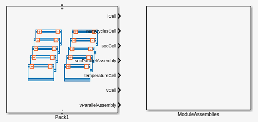
The Simscape models of your ModuleAssembly and Pack objects are subsystems. You can look inside these subsystems by opening the packLibrary SLX file and double-click the subsystem.