Cascaded RF Systems
This model shows how to use blocks from the RF Blockset™ Equivalent Baseband library to build cascaded RF systems.
Example Model
Fig. 1 Example model of cascaded RF systems:

Simulation Results
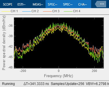
In the first three systems, an amplifier with S-parameters taken from the default.s2p data file is cascaded with different types of transmission lines. The fourth system represents the amplifier itself.
The following figure shows the equivalent baseband frequency response of four RF systems ranging from 1.85 GHz (-250 MHz) to 2.35 GHz (250 MHz).
Fig. 2 Frequency response:

To see the frequency response centered at another RF frequency, change the Center frequency parameter in the Input Port block.
See Also
Equivalent Baseband Transmission Line | LC Bandpass Pi