Unbalanced Load
Load with angle-dependent rotational inertia
Library
Simscape / Driveline / Inertias & Loads
Description
This block models the effects of a load whose rotational inertia varies instantaneously with the rotation angle. Examples include the wobbling of a spinning axle and shaking of an off-center rotating machine. You can specify the load inertia in terms of its rotation path or as an angle-inertia lookup table.
The block provides two rotation path parameterizations. One assumes circular motion of the unbalanced load. The other assumes elliptical motion. In each case, the distance between the unbalanced load and the main rotation axis varies with the rotation angle. The varying distance causes the moment of inertia, given by the parallel-axis theorem, to vary during rotation:
where:
I is the moment of inertia about the main rotation axis.
I0 is the moment of inertia about the intrinsic rotation axis of the unbalanced load.
M is the total mass of the unbalanced load.
r is the distance between the unbalanced load and the main rotation axis.
The angle dependence of the moment of inertia leads to an angle dependence of the inertial torque acting on the unbalanced load:
where:
TI is the inertial torque.
ω is the angular velocity of the load.
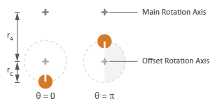
If the load moves in a circular path, its distance to the main rotation axis is given by
where:
rA is the distance between the main rotation axis and the offset rotation axis.
rC is the radius of the circular path.
Circular Rotation Path
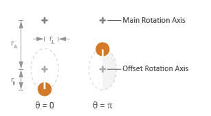
If the load moves in an elliptical path, its distance to the main rotation axis is given by
where:
r∥ is the radius of the elliptical path in line with the distance from the main rotation axis.
r⊥ is radius of the elliptical path perpendicular to the distance from the main rotation axis.
Elliptical Rotation Path
Ports
The block has one conserving rotational port. This port identifies the location of the unbalanced load in a driveline model.
Parameters
Inertia
- Parameterization
Choice of parameterization for modeling the moment of inertia of the unbalanced load. Options include
Circular rotation
,Elliptical rotation
, andBy table lookup
. The default setting isCircular rotation
.Select
Circular rotation
orElliptical rotation
to parameterize the load inertia in terms of the load’s rotation path. SelectBy table lookup
to provide the load inertia directly across its rotation path.- Moment of inertia about own axis
Moment of inertia about the intrinsic rotation axis of the unbalanced load. This moment of inertia is assumed constant throughout simulation. This parameter appears only when Parameterization is set to
Circular rotation
. The default value is1
kg*m2.- Mass
Mass of the unbalanced load. This parameter appears only when Parameterization is set to
Circular rotation
. The default value is1
kg.- Distance from axis to center of rotation
Distance between the main rotation axis and the center of the rotation path. This parameter appears only when Parameterization is set to
Circular rotation
. The default value is0.01
m.- Radius of rotation
Radius of the circular rotation path traversed by the unbalanced load. This parameter appears only when Parameterization is set to
Circular rotation
. The default value is0.01
m.- Radius of rotation inline with distance from axis
Length of the semimajor axis of the elliptical rotation path traversed by the unbalanced load. The semimajor axis is in line with the line segment joining the main rotation axis and the elliptical rotation center. This parameter appears only when Parameterization is set to
Elliptical rotation
. The default value is0.01
m.- Radius of rotation perpendicular to distance from axis
Length of the semiminor axis of the elliptical rotation path traversed by the unbalanced load. The semiminor axis is perpendicular to the line segment joining the main rotation axis and the elliptical rotation center. This parameter appears only when Parameterization is set to
Elliptical rotation
.The default value is0.005
m.- Angle vector
Array of angular positions at which to specify the load inertia. The block calculates the load inertia between the angles specified using linear interpolation. This parameter appears only when Parameterization is set to
By table lookup
. The default vector is[0,pi,3*pi/2]
rad.- Inertia vector
Array of load inertias about the intrinsic rotation axis of the load. Each inertia corresponds to an angle specified in the Angle vector parameter. This parameter appears only when Parameterization is set to
By table lookup
. The default vector is[1,10,1]
kg*m^2.
Initial Conditions
- Initialization
Choice of parameter through which to specify the initial state of the unbalanced load. Options include
Specify angular momentum
andSpecify angular velocity
.- Initial angular momentum
Angular momentum of the unbalanced load at the start of simulation. This parameter appears only when the Initialization parameter is set to
Specify angular momentum
. The default value is0
m^2*kg/s.- Initial angular velocity
Angular velocity of the unbalanced load at the start of simulation. This parameter appears only when the Initialization parameter is set to
Specify angular velocity
. The default value is0
rad/s.- Initial angle
Angular position of the unbalanced load at the start of simulation. The initial angle determines the initial inertia of the unbalanced load. The default value is
0
rad.
Extended Capabilities
Version History
Introduced in R2015b