7-Speed Lepelletier
Clutch schedule for a seven-speed Lepelletier transmission
Libraries:
Simscape /
Driveline /
Transmissions
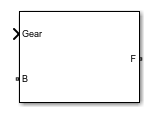
Description
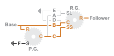
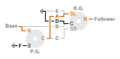
The 7–Speed Lepelletier block consists of one planetary gear set, one Ravigneaux gear set, and six disk friction clutches. The transmission base shaft connects to the ring gear of the planetary gear set. The follower shaft connects to the ring gear of the Ravigneaux gear set. Three of the clutches control the power-flow paths between the planetary and Ravigneaux gear sets. The other three clutches serve as brakes, grounding various gears of the Ravigneaux set to the transmission housing.
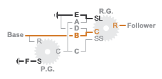
This diagram shows a seven-speed Lepelletier transmission. The labels for the gear components are superimposed on the input and output gears. The table lists the gear and clutch components that are labeled in the diagram.
![]()
| Label | Component |
|---|---|
| P.G. | Planetary gear |
| R.G. | Ravigneaux gear |
| R | Ring gear |
| C | Planet gear carrier |
| S | Sun gear |
| SL | Large sun gear |
| SS | Small sun gear |
| A–C | Forward clutches that control the power-flow path |
| D–F | Forward, braking clutches |
Drive Ratios, Clutch Schedule, and Power Flow
The drive ratio between the transmission input and output shafts follows from the elementary gear ratios specified for the gear blocks. The elementary gear ratios are
and
where:
NPR is the number of teeth in the planetary ring gear.
NPS is the number of teeth in the planetary sun gear.
NRR is the number of teeth in the Ravigneaux ring gear.
NRSL is the number of teeth in the Ravigneaux large sun gear.
NRSS is the number of teeth in the Ravigneaux small sun gear.
The table shows the clutch schedule, drive-ratio expressions, drive-ratio default values, and the power-flow diagrams for each gear of the 7-Speed Lepelletier block.
The letters in the clutch schedule columns denote the brakes and clutches. A value
of 1 denotes a locked state and a value of 0
an unlocked state. The clutch schedule generates these signals based on the Gear
port input signal. The signals are scaled through a Gain block and used as actuation
inputs in the clutch blocks.
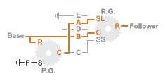
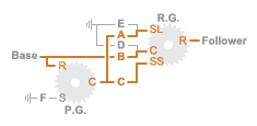
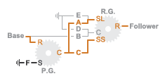
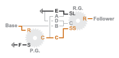
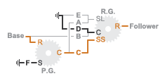
The power-flow diagrams show the power-flow paths between input and output shafts for each gear setting. Power flow is shown in orange. Connections to the transmission housing (a mechanical ground) are shown in black.
| Gear | Clutch Schedule | Drive Ratio Equation | Default Ratio | Power Flow | |||||
|---|---|---|---|---|---|---|---|---|---|
| A | B | C | D | E | F | ||||
| 7 | 0 | 1 | 0 | 0 | 1 | 1 | 0.70 |
| |
| 6 | 1 | 1 | 0 | 0 | 0 | 1 | 0.86 |
| |
| 5 | 1 | 1 | 1 | 0 | 0 | 0 | 1 |
| |
| 4 | 0 | 1 | 1 | 0 | 0 | 1 | 1.17 |
| |
| 3 | 1 | 0 | 1 | 0 | 0 | 1 | 1.63 |
| |
| 2 | 0 | 0 | 1 | 0 | 1 | 1 | 2.43 |
| |
| 1 | 0 | 0 | 1 | 1 | 0 | 1 | 4.31 |
| |
| R | 1 | 0 | 0 | 1 | 0 | 1 | -3.82 |
| |
Examples

Transmission Testbed
A testbed with interchangeable transmissions. The transmission models vary from classic four speed transmissions to modern seven, eight, nine, and ten speed configurations. The efficiency and drive ratio can be adjusted by varying the components in each individual transmission configuration. The transmission choices are held in a variant subsystem and are selected by either using the hyperlinks in the model or right-clicking the Transmission subsystem, selecting Variant -> Override using, and the desired variant.
Ports
Input
Conserving
Parameters
Extended Capabilities
Version History
Introduced in R2015a
See Also
4-Speed CR-CR | 4-Speed Ravigneaux | 6-Speed Lepelletier | 8-Speed | 9-Speed | 10-Speed