manipulatorStateSpace
Description
The manipulatorStateSpace object represents the joint configuration
state space of a rigid body tree robot model. For a given rigidBodyTree object, the nonfixed joints in the rigid body tree model form the
state space. When sampling the state or specifying bounds, the values of the state vector
correspond to joint positions that define a joint configuration with
dimension equal to the NumStateVariables property.
Typically, the manipulator state space works with sampling-based path planners like the
plannerRRT (Navigation Toolbox) and plannerBiRRT (Navigation Toolbox) objects.
To sample and validate paths for manipulators, combine the state space with a state validator
manipulatorCollisionBodyValidator object. Because the
manipulatorStateSpace object derives from the nav.StateSpace (Navigation Toolbox) class,
and is specified in the StateSpace property of the path planners.
To plan paths for manipulators using only Robotics System Toolbox™, see the manipulatorRRT
object.
Creation
Syntax
Description
manipSS = manipulatorStateSpace
manipSS = manipulatorStateSpace(robot)rigidBodyTree object, robot.
manipSS = manipulatorStateSpace(robot,numStateVariables)
Properties
Object Functions
distance | Distance between states |
enforceStateBounds | Limit state to state space bounds |
sampleUniform | Sample state using uniform distribution |
sampleGaussian | Sample state using Gaussian distribution |
interpolate | Interpolate between states |
Examples
Generate states to form a path, validate motion between states, and check for self-collisions and environmental collisions with objects in your world. The manipulatorStateSpace object represents the joint configuration space of your rigid body tree robot model, and can sample states, calculate distances, and enforce state bounds. The manipulatorCollisionBodyValidator object validates the state and motion based on the collision bodies in your robot model and any obstacles in your environment.
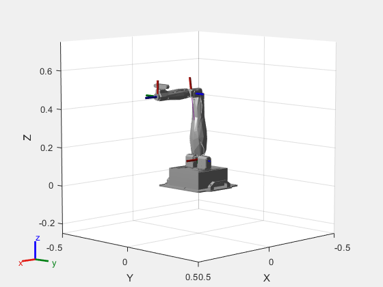
Load Robot Model
Use the loadrobot function to access predefined robot models. This example uses the Quanser QArm™ robot and joint configurations are specified as row vectors.
robot = loadrobot("quanserQArm",DataFormat="row");
figure(Visible="on")
show(robot);
xlim([-0.5 0.5])
ylim([-0.5 0.5])
zlim([-0.25 0.75])
hold on
Configure State Space and State Validation
Create the state space and state validator from the robot model.
ss = manipulatorStateSpace(robot);
sv = manipulatorCollisionBodyValidator(ss,SkippedSelfCollisions="parent");
Set the validation distance to 0.05, which is based on the distance normal between two states. You can configure the validator to ignore self collisions to improve the speed of validation, but must consider whether your robot model has the proper joint limit settings set to ensure it does not collide with itself.
sv.ValidationDistance = 0.05;
sv.IgnoreSelfCollision = true;
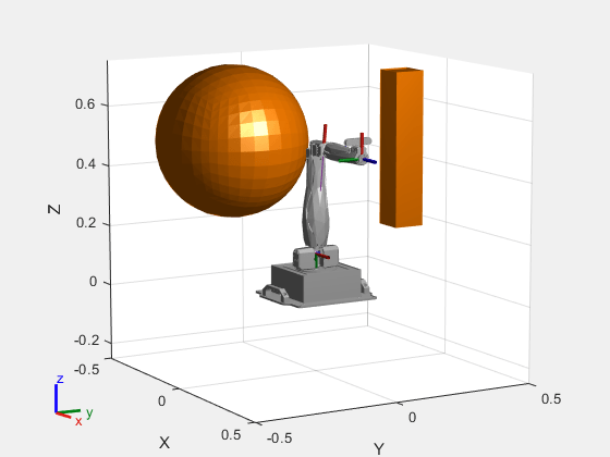
Place collision objects in the robot environment. Set the Environment property of the collision validator object using a cell array of objects.
box = collisionBox(0.1,0.1,0.5); % XYZ Lengths
box.Pose = trvec2tform([0.2 0.2 0.5]); % XYZ Position
sphere = collisionSphere(0.25); % Radius
sphere.Pose = trvec2tform([-0.2 -0.2 0.5]); % XYZ Position
env = {box sphere};
sv.Environment = env;
Visualize the environment.
for i = 1:length(env)
    show(env{i})
end
view(60,10)
Plan Path
Start with the home configuration as the first point on the path.
rng(0); % Repeatable results
start = homeConfiguration(robot);
path = start;
idx = 1;
Plan a path using these steps, in a loop:
Sample a nearby goal configuration, using the Gaussian distribution, by specifying the standard deviation for each joint angle.
Check if the sampled goal state is valid.
If the sampled goal state is valid, check if the motion between states is valid and, if so, add it to the path.
for i = 2:25
    goal = sampleGaussian(ss,start,0.25*ones(4,1));
    validState = isStateValid(sv,goal);

    if validState % If state is valid, check motion between states.
        [validMotion,~] = isMotionValid(sv,path(idx,:),goal);

        if validMotion % If motion is valid, add to path.
            path = [path; goal];
            idx = idx + 1;
        end
    end
end
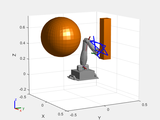
Visualize Path
After generating the path of valid motions, visualize the robot motion. Because you sampled random states near the home configuration, you should see the arm move around that initial configuration.
To visualize the path of the end effector in 3-D, get the transformation, relative to the base world frame at each point. Store the points as an xyz translation vector. Plot the path of the end effector.
eePose = nan(3,size(path,1));

for i = 1:size(path,1)
    show(robot,path(i,:),PreservePlot=false);
    eePos(i,:) = tform2trvec(getTransform(robot,path(i,:),"END-EFFECTOR")); % XYZ translation vector
    plot3(eePos(:,1),eePos(:,2),eePos(:,3),"-b",LineWidth=2)
    drawnow
end
Extended Capabilities
Version History
Introduced in R2021b