Waveform Design and Signal Processing of Stepped Frequency Modulated Radar
This example shows how to design a stepped frequency modulated (FM) waveform, generate I/Q data for a stepped FM radar system, and process the I/Q data for range processing.
Introduction
In some radar systems, such as automotive radar, the radar is required to transceive a waveform with a large bandwidth to achieve fine range resolution, but the sample rate at the radar receiver is low. A very common and effective technique is the linear FM waveform. However, generating linear FM waveform with good linearity over a large bandwidth places high demands on the transmitter analog components.
The stepped FM waveform is an alternative technique for achieving fine range resolution with low sample rate, while avoiding analog FM modulations. A stepped FM waveform is composed of multiple single-frequency signals with frequencies linearly and equally stepped across a large bandwidth. This example demonstrates how to design, simulate and process the stepped FM waveform to satisfy design requirements. The design requirements include:
Range requirements: achieve a maximum unambiguous range of 500 meters and a range resolution of 2 meters.
Detection requirements: detect non-fluctuating targets with a radar cross section (RCS) greater than or equal to 1 square meter, up to the maximum unambiguous range, with a probability of detection of 0.99 and a probability of false alarm of 1e-4.
Waveform and Transceiver Definitions
Define Stepped FM Waveform
Assume that the radar operates at 1 GHz in a free space environment. Use the helperSteppedFMParameter helper function to derive the stepped FM waveform parameters from the specified range requirements.
% Physical parameters
rng('default');                                 % Set random number generator for repeatable results
c = physconst('LightSpeed');                    % Propagation speed (m/s)
fc = 1e9;                                       % Carrier frequency (Hz)
lambda = freq2wavelen(fc,c);                    % Carrier Wavelength (m)

% Range requirements
rangeMax = 500;                                 % Maximum unambiguous range (m)
rangeRes = 2;                                   % Required range resolution (m)

% Waveform parameters
dutyCyc = 0.5;                                  % Duty cycle
[Nstep,fstep,fs,prf,pulseWidth] = helperSteppedFMParameter(rangeMax,rangeRes,dutyCyc);
Define the stepped FM waveform using phased.SteppedFMWaveform object. Configure the stepped FM waveform using the derived waveform parameters.
% Configure the stepped FM waveform
sfmwav = phased.SteppedFMWaveform('NumSteps',Nstep,'FrequencyStep',fstep,...
    'SampleRate',fs,'PRF',prf,'PulseWidth',pulseWidth);
Plot the spectrum of the first 15 steps.
helperViewSteppedFMSpectrum(sfmwav);

Model Radar Transceivers
The radar uses a single isotropic antenna to transmit and uses a single isotropic antenna to receive the radar signals. Determine the radar transmit peak power according to the detection requirements. For more information on the peak transmit power specification, please refer to the example Simulating Test Signals for a Radar Receiver.
% Construct transmit and receive antenna element
antElmnt = phased.IsotropicAntennaElement;      % Isotropic antenna
antGain = 20;                                   % Antenna gain (dB)

% Detection requirements
pd = 0.99;                                      % Probability of detection
pfa = 1e-4;                                     % Probability of false alarm

% Determine minimum required SNR from detection requirements
snrMin = albersheim(pd,pfa);                    % Minimum required SNR (dB)

% Specify minimum target RCS
minRCS = 1;                                     % Minimum target RCS (m^2)

% Signal duration in stepped FM waveform
sigtau = Nstep*pulseWidth;                      % Signal duration in waveform (s)

% Determine radar transmit peak power from radar equation
txPkPower = radareqpow(lambda,...
    rangeMax,snrMin,sigtau,...
    'RCS',minRCS,'Gain',antGain);               % Transmit peak power (W)
Model the radar's monostatic transceiver using radarTransceiver and configure the radar to use a stepped FM waveform.
% Model radar monostatic transceiver
radar = radarTransceiver('Waveform',sfmwav);
radar.Transmitter = phased.Transmitter('PeakPower',txPkPower,'Gain',antGain);
radar.TransmitAntenna = phased.Radiator('Sensor',antElmnt,'OperatingFrequency',fc);
radar.ReceiveAntenna = phased.Collector('Sensor',antElmnt,'OperatingFrequency',fc);
radar.Receiver = phased.ReceiverPreamp('Gain',antGain,'SampleRate',sfmwav.SampleRate);
Scenario Setup
Define a scenario with a stationary radar and 3 moving targets using radarScenario. The scenario updates in each frequency step, and the scenario duration is the duration of a stepped FM waveform.
% Create a radar scenario
scene = radarScenario('UpdateRate',sfmwav.PRF,'StopTime',(sfmwav.NumSteps-1)/sfmwav.PRF);
Set and visualize the positions and velocities of radar and targets below.
% Set positions of radar and targets
[radarPlatform,tgtPlatform] = helperPlatformSetup(radar,scene);

% Visualize positions of radar and targets
helperViewRadarScenario(radarPlatform,tgtPlatform);
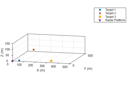
Show the initial positions of the targets relative to the radar.
% Targets' initial positions
[tgtRange,tgtDOA] = helperViewInitialPosition(radarPlatform,tgtPlatform)
tgtRange = 1×3
62 214 327
tgtDOA = 2×3

   42.0000         0   16.0000
         0   30.0000         0
Receiver Signal Processing
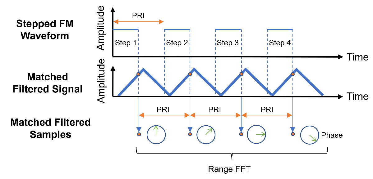
The receiver signal processing flow is summarized using the following diagram. First, each step of the received signal is passed to its matched filter. Next, sample one point on the matched filter output in each step with the sample interval equal to the pulse repetition interval (PRI) of the stepped FM waveform. Finally, perform fast Fourier transform (FFT) on the samples to obtain the range response and use a constant false alarm rate (CFAR) detector to detect targets' ranges.
Receiving I/Q data
To receive the I/Q data, advance the radar scenario with the duration equal to the PRI using advance and get the received I/Q signal in each step from the radar scenario using receive.
% Number of samples in a PRI
Npri = floor(sfmwav.SampleRate/prf);

% Assemble the received I/Q data
Xrec = zeros(Npri,Nstep);

% Initialize step index
stepIdx = 1;

% Advance radar scenario for in each frequency step
while advance(scene)
    % Get the received signal
    rxSig = receive(scene);

    % Record the received signal
    Xrec(:,stepIdx) = rxSig{1};

    % Update step index
    stepIdx = stepIdx + 1;
end
Matched Filtering
A simple pulse matched filter is applied to process the received data in each step. Then, sample the matched filter signal in each step at the matched filter delay and the sample rate is equal to the pulse repetition frequency (PRF) of the stepped FM waveform. The matched filtered samples have significantly higher amplitudes than the received raw I/Q data.
% Get matched filter coefficient for the stepped FM waveform
mfCoeff = getMatchedFilter(sfmwav);

% Assemble the matched filtered data
Xmf = zeros(Npri,Nstep);

% Match filtering for each step
for stepIdx = 1:Nstep
    % Define matched filter for each step
    mf = phased.MatchedFilter('Coefficients',mfCoeff(:,stepIdx));

    % Perform matched filtering
    Xmf(:,stepIdx) = mf(Xrec(:,stepIdx));
end

% Get matched filter delay
mfDelay = size(mfCoeff,1);

% Sample in each frequency step at the matched filter delay
XmfSample = reshape(Xmf(mfDelay,:),Nstep,[]);
Range Processing
The linear increase of the frequency in different steps introduces linear phase shifts on the matched filter samples for each target. The linear phase shift change speed of a target is linearly proportional to the target's range. This allows the stepped FM radar to measure the ranges of the targets via measuring the phase shifts, which can be efficiently implemented using range FFT.
Apply range FFT on the sampled data using phased.RangeResponse. As the sampled data are sampled with intervals equal to the PRI of the stepped FM waveform, the sample rate configured in phased.RangeResponse is the PRF of the stepped FM waveform. The sweep slope of the stepped FM waveform is defined and configured as the step frequency divided by the PRI.
% Number of range samples
Nrange = 2^nextpow2(Nstep);

% Define range response
rngresp = phased.RangeResponse('RangeMethod','FFT',...
    'RangeFFTLengthSource','Property','RangeFFTLength',Nrange,...
    'SampleRate',sfmwav.PRF,...
    'SweepSlope',sfmwav.FrequencyStep*sfmwav.PRF,...
    'ReferenceRangeCentered',false);

% Calculate the range response of the sampled I/Q data
[Xrng,rngGrid] = rngresp(conj(XmfSample));
CFAR Detection
Apply the CFAR detector on the range response for detecting the ranges of the targets.
% CFAR detector setup
cfarDetector = phased.CFARDetector('NumGuardCells',6,...
    'NumTrainingCells',10,'ProbabilityFalseAlarm',pfa,...
    'ThresholdOutputPort',true);

% Range spectrum
rngSpectrum = abs(Xrng).^2;

% CFAR detection on range spectrum
[cfarDetectResult,cfarDetectThresh] = cfarDetector(rngSpectrum,1:Nrange);

% Plot range response pattern and CFAR detection result
helperViewDetectionResult(rngSpectrum,rngGrid,cfarDetectResult,cfarDetectThresh);
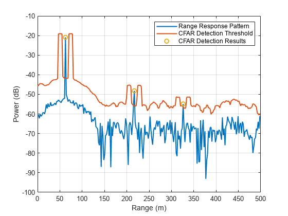
From the CFAR detection result, we can clearly observe 3 targets. The detected ranges are displayed below.
rngDetected = rngGrid(cfarDetectResult)'
rngDetected = 1×3

   62.5000  216.7969  326.1719
Summary
In this example, you learned how to design a stepped FM waveform to meet desired performance requirements. You learned how to generate and process the stepped FM I/Q data to obtain range response.
Reference
[1] M. A. Richards. Fundamentals of Radar Signal Processing, Second., New York: McGraw Hill, 2014, pp. 188–194.
[2] M. A. Richards, W. L. Melvin, J. A. Scheer, J. Scheer. Principles of Modern Radar: Advanced Techniques, Volume 2. Institution of Engineering and Technology, 2012, pp. 58-69.
[3] N. Levanon. "Stepped-frequency Pulse-train Radar Signal," in IEE Proceedings-Radar Sonar and Navigation 149, no. 6, 2002.
[4] D. A. Noon. "Stepped-frequency Radar Design and Signal Processing Enhances Ground Penetrating Radar Performance," 1996.
Helper Functions
helperSteppedFMParameter Function
function [nstep,fstep,fs,prf,pulseWidth] = helperSteppedFMParameter(rangeMax,rangeRes,dutyCyc)
c = physconst('LightSpeed');                  % Propagation speed (m/s)

% Determine step frequency from the required maximum range
fstep = rangeres2bw(rangeMax,c);              % Step frequency (Hz)

% Determine the waveform bandwidth from the required range resolution
bw = rangeres2bw(rangeRes,c);                 % Bandwidth (Hz)

% Determine RF sample rate from bandwidth
fs = 2*bw;                                    % RF sample rate (Hz)

% Determine number of frequency steps in the stepped FM waveform
nstep = round(bw/fstep);                      % Number of frequency steps

% Determine pulse width
pulseWidth = 1/fstep;                         % Pulse width (s)

% Determine fast-time PRF
prf = dutyCyc/pulseWidth;                     % Fast-time PRF (Hz)
end
helperPlatformSetup Function
function [radarPlatform,tgtPlatform] = helperPlatformSetup(radar,scene)
% Initialize radar position and velocity
radarPos = [0; 0; 0];
radarVel = [0; 0; 0];

% Define radar platform
radarTrajectory = kinematicTrajectory('Position',radarPos,'Velocity',radarVel);
radarPlatform = platform(scene,'Trajectory',radarTrajectory,'Sensors',radar);

% Initialize targets' positions and velocities
ntgt = 3;                                    % Number of targets
tgtRcs = [2.2 1.6 2.8];                      % Targets' RCSs (m^2)
tgtRng = [62 214 327];                       % Targets' ranges (m)
tgtAz  = [42 0 16];                          % Targets' azimuth angle (deg)
tgtEl  = [0 30 0];                           % Targets' elevation angle (deg)
[tgtx, tgtY, tgtZ] = sph2cart(deg2rad(tgtAz),deg2rad(tgtEl),tgtRng);
tgtPos = [tgtx; tgtY; tgtZ];
tgtVel = [30 120 -60;0 10 0;0 0 0];

% Define target platform
tgtPlatform = cell(ntgt, 1);
fc = radar.TransmitAntenna.OperatingFrequency;
for tgtIdx = 1:ntgt
    tgtTrajectory = kinematicTrajectory('Position',tgtPos(:,tgtIdx),'Velocity', tgtVel(:,tgtIdx));
    tgtRcsSignature = rcsSignature('FluctuationModel','Swerling0',...
        'Pattern',[tgtRcs(tgtIdx),tgtRcs(tgtIdx)],...
        'Azimuth',[-180 180],'Elevation',[-90 90],'Frequency',[fc fc]);
    tgtPlatform{tgtIdx} = platform(scene, 'Trajectory', tgtTrajectory, ...
        'Signature', tgtRcsSignature);
end
end
You can also select a web site from the following list:
Americas
- América Latina (Español)
- Canada (English)
- United States (English)
Europe
- Belgium (English)
- Denmark (English)
- Deutschland (Deutsch)
- España (Español)
- Finland (English)
- France (Français)
- Ireland (English)
- Italia (Italiano)
- Luxembourg (English)
- Netherlands (English)
- Norway (English)
- Österreich (Deutsch)
- Portugal (English)
- Sweden (English)
- Switzerland
- United Kingdom (English)