Radar Target Emulator with HDL Coder
This example demonstrates an HDL compatible radar target emulator. This model can be deployed onto a field-programmable-gate-array (FPGA) to emulate radar target returns in real time for hardware-in-the-loop (HIL) testing.
Introduction
The model demonstrated in this example emulates a few dominant behavioral characteristics of a radar point target:
Delay due to target range.
Doppler shift due to target radial velocity.
Signal attenuation due to factors such as target range and radar cross section (RCS).
You can update this simple model to include additional effects to test real radar systems. For example, you could modify the signal attenuation to contain information about the two-way antenna pattern that is used by the radar system.
This emulator is intended to be deployed on an FPGA that receives I/Q samples that are captured by an analog-to-digital converter (ADC) at the input. The emulator transforms incoming samples according to target characteristics. These transformed samples would then be re-transmitted through a digital-to-analog converter (DAC) at the output of the FPGA, thereby emulating a simple radar channel.
See Radar Target Emulation on NI USRP Radio (Wireless Testbench) for an example on deploying this model to a real FPGA.
Target Emulator Model
In this section we briefly introduce the components of the target emulator. In addition to the model described in this section, there is an associated helper function called helperSimulationSetup that sets up all of the required parameters for the simulation.
The model in this example is segregated into four key sections:
Radio Receive - This subsystem simulates the received samples. When deployed, this subsystem would be replaced with samples captured by the ADC.
MATLAB - This section converts the target characteristics set in MATLAB into the correct register format required by the target emulator.
Radio Transmit - This section just contains the output samples for the model. When deployed, this section would be updated to write the output samples to the DAC.
Target Emulator - This subsystem modifies the input samples according to the target characteristics. This is the subsystem that would be deployed onto your FPGA.
open_system('slexRADARTargetEmulator');

The Target Emulator subsystem performs the key operations on the collected input samples to emulate real targets. As configured, this subsystem allows the simulation of eight separate radar targets.
open_system('slexRADARTargetEmulator/Target Emulator');
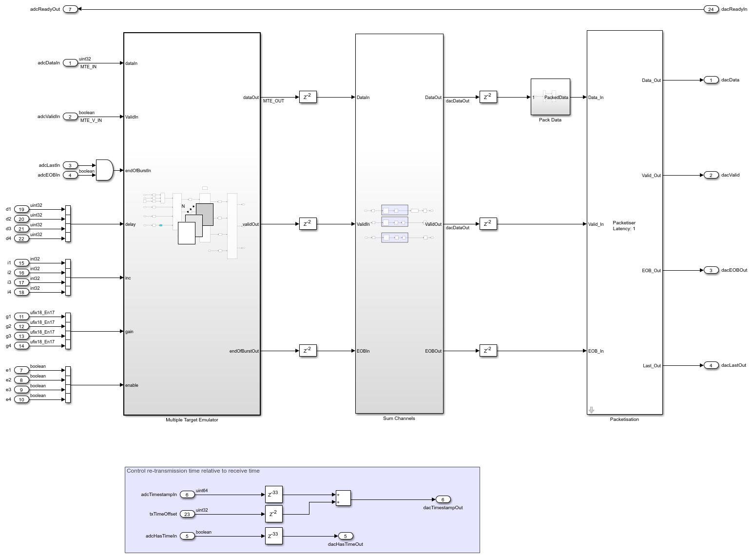
There are two key blocks within the Target Emulator subsystem:
Multiple Target Emulator - This is the key subsystem that modifies and sums the incoming samples for each emulated target that is enabled.
Data Bus Packetisation - This block creates packets for writing to the DAC.
The Multiple Target Emulator has four subsystems:
open_system('slexRADARTargetEmulator/Target Emulator/Multiple Target Emulator');
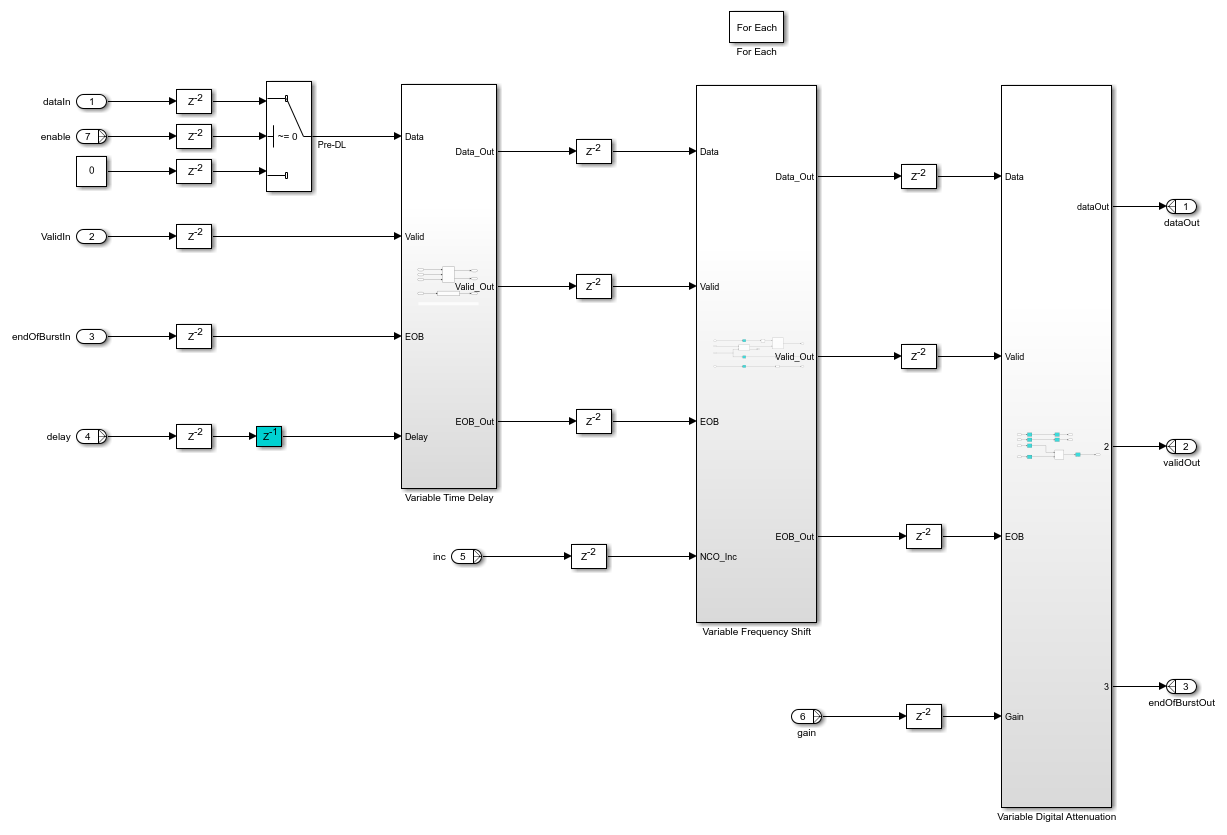
These four subsystems each perform one of the key signal transformations:
Variable Time Delay - This subsystem delays the input sample to simulate propagation delay based on the target range.
Variable Frequency Shift - This subsystem applies a frequency shift to the samples to simulate Doppler shift based on the target radial velocity with respect to the radar.
Variable Digital Attenuation - This subsystem attenuates the input sample to simulate signal power loss due to the propagation channel and target RCS. Other effects such as antenna pattern could also be wrapped into this attenuation values.
Sum Channels - This subsystem combines the response of each of the eight targets.
Simulation Using Target Emulator
Now that we have investigated the layout of the key components within the target emulator, run the target emulator in Simulink. The registers that define the target characteristics are driven from a MATLAB model. The MATLAB model uses multiple platform within a radarScenario to advance eight radar targets through a simple simulation. Run this simulation updating the target registers as the radarScenario is stepped forward in time. Visualize the range-Doppler response of the emulated scenario at each step. This represents an approach that you could use to control the registers on the target emulator once deployed onto a real FPGA.
The following block of code sets up a radarScenario with eight targets. The targets are assumed to be airplanes based on the operating ranges and RCS. Each target is placed at different starting ranges and is configured with a unique trajectory.
% Create scenario with an update rate of 10 s so that we can visualize
% target motion. Run for 2 simulation frames to demonstrate target motion.
% When deploying to an actual FPGA you may want to set the update rate to
% be the same as the length of a coherent processing interval.
nSteps = 1;
tUpdate = 10;
tRun = nSteps*tUpdate;
scenario = radarScenario(UpdateRate=1/tUpdate,StopTime=tRun);

% Set the radar position to the origin.

radarPosition = [0 0 0];
Import the mean radar cross section (RCS) for a Boeing 737 and assign it to an RCS signature object. Use this RCS for each of the targets to model them as aircraft.
load('RCSSignatureExampleData.mat','boeing737');
planeRcsSignature = rcsSignature( ...
    Pattern=boeing737.RCSdBsm, ...
    Azimuth=boeing737.Azimuth, ...
    Elevation=[-90 90]);
Add each target to the scenario as a platform object with a unique trajectory and the imported aircraft RCS signature.
Use the kinematicTrajectory function to set the location of the first target at 5 km ground range, 2 km height, moving away from the radar at 200 m/s.
t1Pos = [5e3 0 2e3];
t1Vel = [200 0 0];
t1 = platform(scenario);
t1.Signatures = {planeRcsSignature};
t1.Trajectory = kinematicTrajectory(Position=t1Pos,Velocity=t1Vel);
Set the location of the second target at 7.5 km ground range, 1 km height, moving towards the radar at 150 m/s.
t2Pos = [7.5e3 0 1e3];
t2Vel = [-150 0 0];
t2 = platform(scenario);
t2.Signatures = {planeRcsSignature};
t2.Trajectory = kinematicTrajectory(Position=t2Pos,Velocity=t2Vel);
Set the location of the third target to diagonal (7.5 km in x, 3 km in y), 2.5 km height, flying in a straight line so that radial velocity changes constantly.
t3Pos = [7.5e3 3e3 2.5e3];
t3Vel = [0 -250 0];
t3 = platform(scenario);
t3.Signatures = {planeRcsSignature};
t3.Trajectory = kinematicTrajectory(Position=t3Pos,Velocity=t3Vel);
Use the helperRadarTargetCircularWaypoints function to set the fourth target flying in a circle around the radar at 4 km, so that it's radial speed is always 0.
t4Dist = 4e3;
t4 = platform(scenario);
t4.Signatures = {planeRcsSignature};
t4.Trajectory = helperRadarTargetCircularWaypoints(t4Dist,radarPosition,tRun);
Use the kinematicTrajectory function to set the location of the fifth target at 3 km ground range, 400m height, moving away from the radar at 180 m/s.
t5Pos = [3e3 0 0.4e3];
t5Vel = [180 0 0];
t5 = platform(scenario);
t5.Signatures = {planeRcsSignature};
t5.Trajectory = kinematicTrajectory(Position=t5Pos,Velocity=t5Vel);
Set the location of the sixth target at 800m ground range, 800m height, moving away from the radar at 90 m/s.
t6Pos = [0.8e3 0 0.8e3];
t6Vel = [90 0 0];
t6 = platform(scenario);
t6.Signatures = {planeRcsSignature};
t6.Trajectory = kinematicTrajectory(Position=t6Pos,Velocity=t6Vel);
Set the location of the seventh target to diagonal (350m in x, 1 km in y), 2.5 km height, flying in a straight line so that radial velocity changes constantly.
t7Pos = [0.35e3 1e3 2.5e3];
t7Vel = [0 100 0];
t7 = platform(scenario);
t7.Signatures = {planeRcsSignature};
t7.Trajectory = kinematicTrajectory(Position=t7Pos,Velocity=t7Vel);
Use the circular waypoint helper function to set the eighth target flying in a circle around the radar at 9 km, so that it's radial speed is always 0.
t8Dist = 9e3;
t8 = platform(scenario);
t8.Signatures = {planeRcsSignature};
t8.Trajectory = helperRadarTargetCircularWaypoints(t8Dist,radarPosition,tRun);
Customize the simulation by editing the helperRadarTargetSimulationSetup.m function.
Run the target simulator setup helper function to get the default simulation parameters. Later in the example you will update the simulation parameters for each of the targets.
sl_in = helperRadarTargetSimulationSetup();

% Set max gain to a target at 3 km
maxGain = helperRadarTargetMaxGain(3e3,max(planeRcsSignature.Pattern),sl_in.lambda);

% Create a figure for plotting
f = tiledlayout("horizontal");

% Create a range-Doppler response object for processing data
rdResponse = phased.RangeDopplerResponse(...
    'DopplerFFTLengthSource','Property', ...
    'DopplerFFTLength',sl_in.VelDimLen, ...
    'PRFSource','Property', 'PRF',sl_in.PRF,...
    'SampleRate',sl_in.Fs,'DopplerOutput','Speed', ...
    'OperatingFrequency',sl_in.Fc);

% Create a 2D CFAR object for detection generation
cfar = phased.CFARDetector2D(GuardBandSize=[25 1],TrainingBandSize=[10 1],...
    ProbabilityFalseAlarm=1e-4);

cStep = 1;
while advance(scenario)
    % Get the RCS, range, and radial speed for each target
    [targetEnabled,targetRCS,targetRange,targetSpeed] = helperRadarTargetInformation(radarPosition,sl_in.Fc,t1,t2,t3,t4,t5,t6,t7,t8);

    % Call the simulation setup function to adjust target parameters
    sl_in = helperRadarTargetSimulationSetup(targetEnabled,targetRCS,targetRange,targetSpeed,maxGain);

    % Run the simulation
    sl_out = sim('slexRADARTargetEmulator');

    % Visualize the output including the Range-Doppler response,
    % detections, and actual target locations
    ax = nexttile(f);
    helperVisualizeRadarTargetSimulation(sl_out,sl_in,rdResponse,cfar,cStep,ax);
    cStep = cStep + 1;
end
### Searching for referenced models in model 'slexRADARTargetEmulator'.
### Total of 1 models to build.
### Building the rapid accelerator target for model: slexRADARTargetEmulator
### Successfully built the rapid accelerator target for model: slexRADARTargetEmulator
### Searching for referenced models in model 'slexRADARTargetEmulator'.
### Total of 1 models to build.
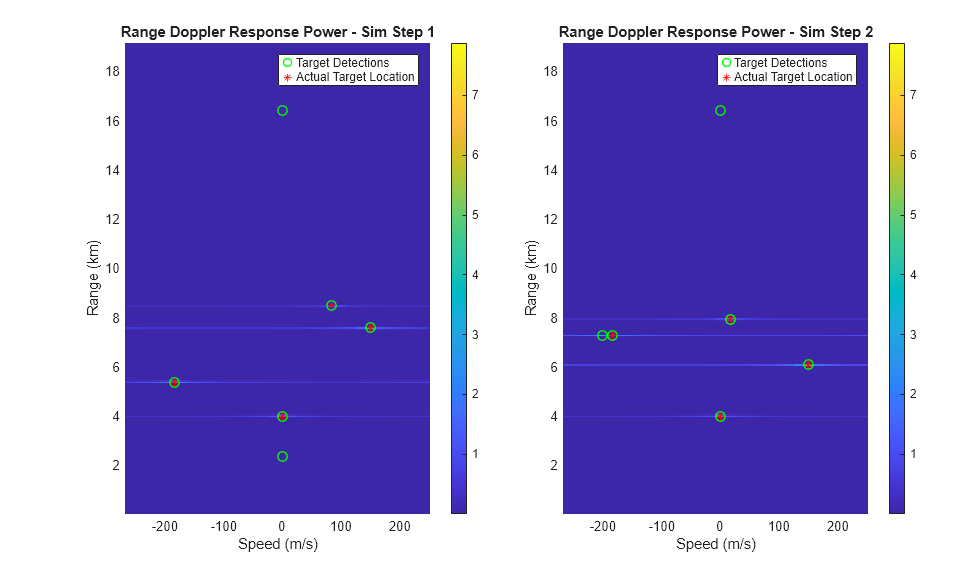
The target returns are apparent in the range-Doppler response at each time step. Using a constant false alarm rate (CFAR) detector, there is a detection at each true target location. The false alarms in the range-Doppler sidelobes could potentially be mitigated with additional tuning of the CFAR detector.
Conclusion
This example demonstrates an HDL compatible radar target emulator. Target detections are calculated using the target emulator for a simulated radar scenario with eight targets. This model can be deployed to an FPGA for real-time radar channel emulation.