Run-Time Data Collection by Using External Mode Logging
Generate code by using external mode logging. Download the generated code with the external mode logging function to the target Programmable Logic Controller (PLC) and collect run-time data. Visualize and monitor the collected run-time data by using Simulation Data Inspector and an Open Platform Communications (OPC) server.
Target Integrated Development Environments (IDEs)
Rockwell Automation® Studio 5000® IDE
Rockwell Automation® RSLinx® Classic
Open Model
Open the ext_demo1.slx model. The model consists of two children subsystems S1 and S2, a MATLAB Function block, and a Stateflow® chart.
uiopen('ext_demo1.slx',1);
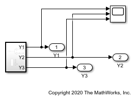
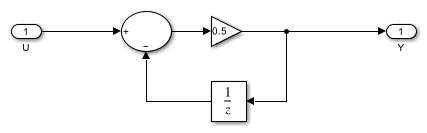
The S1 and S2 children subsystems are identical and contain a simple feedback loop.
mdl_1 = 'ext_demo1/Subsystem/S1';
open_system(mdl_1);
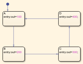
The Stateflow chart is a simple state machine that has four states. The states change the value of the variable out during every simulation timestamp.
mdl_2 = 'ext_demo1/Subsystem/Chart';
open_system(mdl_2);
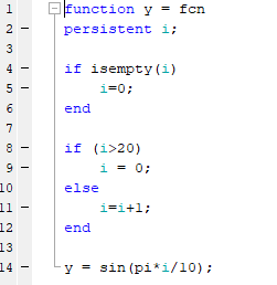
The MATLAB Function block produces code to generate a sine wave. The sine wave is the input to the S1 and S2 subsystems.
mdl_3 = 'ext_demo1/Subsystem/MATLAB Function';
open_system(mdl_3);
External Mode Logging and Code Generation
External mode logging can save system states, outputs, and simulation time at each model execution step. The data is written to a MAT-file. Collect run-time data for the variables in the MAT-file by running the generated code, which contains the logging function in a target IDE.
To enable external mode logging and generate code:
Open the Simulink® PLC Coder™ app.
Select the
Subsystemblock. In the PLC Code tab, click Settings.On the PLC Code Generation pane, set Target IDE to
Rockwell Studio 5000: AOI.On the Interface pane, select Generate Logging Code. Click OK.
In the PLC Code tab, click Generate PLC Code.
The software also generates a plc_log_data.mat file during code generation.
Download Code and Configure RSLinx OPC Server
To download and set up the OPC server:
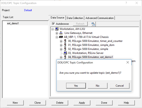
Open the
ext_demo1.ACDfile by using the Studio 5000 IDE. Compile the file and download it to your target PLC.Start RSLinx and select DDE/OPC > Topic Configuration. Click New, and in the dialog box, enter
ext_demo1as the topic name. On the Data Source tab, select your target PLC. Click Yes.
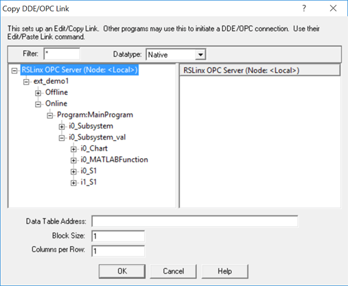
To verify the OPC server setup, in RSLinx select Edit > Copy DDE/OPC Link. If iO_Subsystem_val is present, the server configuration is complete.
Stream and Display Run-Time Data
You can stream and display the logging data through Simulation Data Inspector by using Simulink PLC Coder external mode commands. Use plcdispextmodedata to display the contents of the plc_log_data MAT-file.
cd plcsrc
plcdispextmodedata plc_log_data.mat
Connect to the OPC server and stream logging data by using the plcrunextmode function.
plcrunextmode('localhost','studio5000','ext_demo1','plc_log_data.mat')
You must have the RSLinx classic version to copy the DDE/OPC link. The RSLinx Classic Lite version does not work.