Model and Generate Ladder Logic Code for Industrial Tank Level Control System
In this example, you use Simulink PLC Coder™ to model, simulate, and generate a ladder logic-based controller for the level control of an industrial tank. The ladder logic controls the tank level by using inputs from a low-level and high-level sensor in the tank to control a valve that empties the tank and a pump that fills the tank. After you simulate and verify the controller operation, generate code for your controller.
Open Model
Open the model.
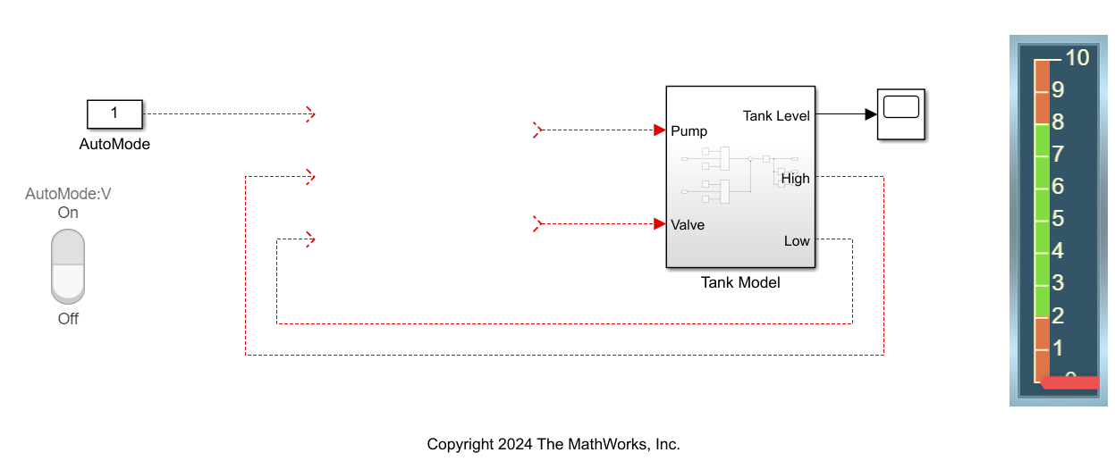
open_system("PumpLadder_Start");The model consists of a subsysten named Tank Model that models the tank dynamics, sensors, pump, and valve. To complete the model, you must insert a PLC Controller Suite block and model the ladder logic to control the tank level.

Create a Ladder Logic Controller
Use the Simulink PLC Coder™ ladder diagram block library to model and simulate ladder logic elements. To access the library, at the MATLAB command line, enter:
plcladderlib
Use the plcloadtypes function to load the custom ladder logic data types. At the MATLAB command line, enter:
plcloadtypes
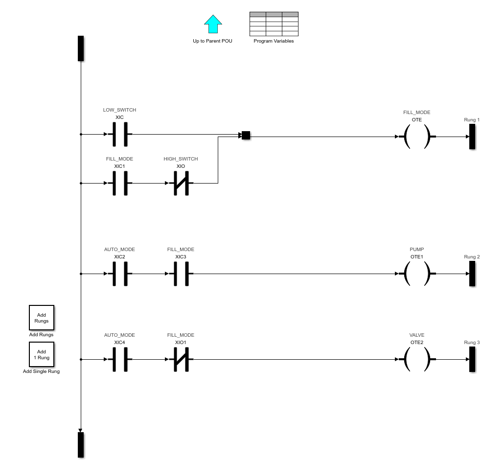
Select and add a PLC Controller Suite block from the ladder logic library. The PLC Controller Suite block represents a virtual programmable logic controller (PLC). After you add the block, to navigate to the ladder diagram section, open PLC Controller Suite block, Task block, and then the Program block. Use the elements in the ladder diagram block library to create the ladder diagram in this image.

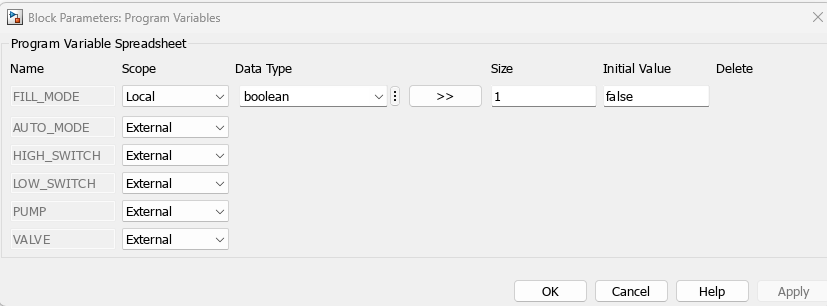
Double-click the Program Variables block and set AUTO_MODE, HIGH_SWITCH, LOW_SWITCH, PUMP, and VALVE to External.

Open the PLC Controller Suite block and double-click the Controller Tags block. Set AUTO_MODE, HIGH_SWITCH, and LOW_SWITCH to Input_Symbol. Set PUMP and VALVE to Output_Symbol.

Connect the PLC Controller Suite block as shown in this image.

Simulate Model and Generate Code
When you simulate the model with the AutoMode block in the On position, the red indicator in the tank level display slides up and down. When the tank level is at two, the ladder logic turns on the pump and fills the tank until the level reaches eight. When the level exceeds or reaches eight, the ladder logic turns on the valve and drains the tank until the level reaches two. When the level is less than or equal to two, the pump turns on and fills the tank. When the AutoMode block is in the Off position, the tank level stays constant. After you verify your ladder logic operation, generate code for your tank level controller.
To generate code in the Apps tab, select PLC Coder. In the PLC Code tab, click Settings > PLC Code Generation Settings. Change the Target IDE parameter to Rockwell Studio 5000: AOI. Click OK. Click Generate PLC Code.
Alternatively, generate code by using the plcgeneratecode function.
plcgeneratecode("PumpLadder_Start/PLC Controller Suite")