Main Content

importGeometry

Import geometry from STL or STEP file

Description

gm = importGeometry(geometryfile) creates a geometry object from the specified STL or STEP geometry file. A geometry imported from an STL file can be 3-D or planar. A geometry imported from a STEP file must be 3-D.

example

gm = importGeometry(model,geometryfile) also includes the geometry in the model container.

importGeometry(model,___) creates a geometry object from the specified STL or STEP geometry file and includes the geometry in the model container.

example

___ = importGeometry(___,Name=Value) creates a geometry object using one or more name-value arguments. Use this syntax with any of the argument combinations from the previous syntaxes.

example

Examples

collapse all

Since R2021a

Create a geometry object from an STL geometry file.

gm = importGeometry("ForearmLink.stl");

Plot the geometry.

pdegplot(gm)

Figure contains an axes object. The axes object contains 6 objects of type quiver, text, patch, line.

Import a planar STL geometry and include it in a PDE model. When importing a planar geometry, importGeometry converts it to a 2-D geometry by mapping it to the xy-plane.

Create a PDEModel container.

model = createpde;

Import a geometry into the container.

importGeometry(model,"PlateHolePlanar.stl")
ans = 
  DiscreteGeometry with properties:

       NumCells: 0
       NumFaces: 1
       NumEdges: 5
    NumVertices: 5
       Vertices: [5x3 double]

Plot the geometry with the edge labels.

pdegplot(model,"EdgeLabels","on")

Figure contains an axes object. The axes object contains an object of type line.

Create a geometry object from a STEP geometry file.

gm = importGeometry("BlockWithHole.step");

Plot the geometry.

pdegplot(gm,"FaceAlpha",0.3)

Figure contains an axes object. The axes object contains 6 objects of type quiver, text, patch, line.

Now import the same geometry while specifying the relative sag. You can use this parameter to control the accuracy of the geometry import.

gm = importGeometry("BlockWithHole.step","MaxRelativeDeviation",10);

Plot the geometry.

figure
pdegplot(gm,"FaceAlpha",0.3)

Figure contains an axes object. The axes object contains 6 objects of type quiver, text, patch, line.

Input Arguments

collapse all

Model container, specified as a PDEModel object, ThermalModel object, StructuralModel object, or ElectromagneticModel object.

Example: model = createpde(3)

Example: thermalmodel = createpde(thermal="steadystate")

Example: structuralmodel = createpde(structural="static-solid")

Example: emagmodel = createpde(electromagnetic="electrostatic")

Path to STL or STEP file, specified as a string scalar or a character vector ending with the file extension ".stl", ".stp", or ".step". Use can also use the uppercase extensions ".STL", ".STP" or ".STEP", or any combinations of uppercase and lowercase letters in these extensions.

Example: "../geometries/Carburetor.stl"

Data Types: string | char

Name-Value Arguments

Specify optional pairs of arguments as Name1=Value1,...,NameN=ValueN, where Name is the argument name and Value is the corresponding value. Name-value arguments must appear after other arguments, but the order of the pairs does not matter.

Example: gm = importGeometry("AngleBlock.step",MaxRelativeDeviation=5)

Indicator to allow import of self-intersecting geometry from an STL or STEP file, specified as true or false. You also can use 1 or 0 instead of true or false. By default, importGeometry does not check for self-intersections and lets you import such geometries. If you set AllowSelfIntersections to false or 0, importGeometry throws an error for a geometry with self-intersections.

Example: gm = importGeometry("GeometryWithSelfIntersectons.stl",AllowSelfIntersections=true)

Threshold for the dihedral angle between adjacent triangles to indicate the edge and create two separate faces, specified as a number between 10 and 90. Specify the FeatureAngle value in degrees. This name-value argument only works for importing a geometry from an STL file.

If the angle between the triangles exceeds the threshold, the edge becomes a topological (feature) edge separating two faces. If it does not exceed the threshold, importGeometry does not create a topological edge with two separate faces, unless the edge can be created based on other criteria. Instead, importGeometry treats it as one face.

Example: gm = importGeometry("Geometry.stl",FeatureAngle=30)

Relative sag for importing a STEP geometry, specified as a number in the range [0.1,10]. This value controls the accuracy of the geometry import from a STEP file. A relative sag is the ratio between the local absolute sag and the local mesh edge length. The absolute sag is the maximal gap between the mesh and the geometry.

Gap between the curved geometry edge and the straight mesh edge represents the local absolute sag.

Example: gm = importGeometry("AngleBlock.step",MaxRelativeDeviation=5)

Data Types: double

Output Arguments

collapse all

Geometry, returned as a DiscreteGeometry object.

Limitations

  • importGeometry does not allow you to import a multidomain 2-D or 3-D geometry where subdomains have any common points. If the subdomains of the geometry have common points, the toolbox still treats these subdomains as disconnected, without any common interface between them. Each subdomain has its own mesh.

    Because of this limitation, you cannot import nested 3-D geometries directly. As a workaround, you can import a mesh and then create a multidomain geometry from the mesh by using the geometryFromMesh function. See Multidomain Geometry Reconstructed from Mesh.

Tips

  • The STL format approximates the boundary of a CAD geometry by using a collection of triangles, and the importGeometry function reconstructs the faces and edges from this data. Reconstruction from STL data is not precise and can result in a loss of edges and, therefore, the merging of adjacent faces. Typically, lost edges are the edges between two adjacent faces meeting at a small angle, or smooth edges bounding blend surfaces. Usually, the loss of such edges does not affect the analysis workflow.
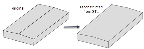
    Comparison of an original CAD geometry and a geometry reconstructed from STL. The geometry reconstructed from STL is missing one of the edges. The two faces adjacent to that edge are merged into one face.

  • Because STL geometries are only approximations of the original CAD geometries, the areas and volumes of the STL and CAD geometries can differ.

Version History

Introduced in R2015a

expand all