Medical Image Coordinate Systems
In medical imaging, there are two distinct coordinate systems: the intrinsic coordinate system and the world, or patient, coordinate system. You can access locations in medical images using the intrinsic coordinate system and the patient coordinate system.
The intrinsic coordinate system defines the voxel space, and the patient coordinate system
defines the anatomical space. To understand the position and orientation of intrinsic
coordinates with respect to the patient, you must transform the data into the patient
coordinate system. You can use the intrinsicToWorldMapping function to obtain the transformation between the
intrinsic coordinates and patient coordinates of a 3-D medical image volume stored as a
medicalVolume
object.
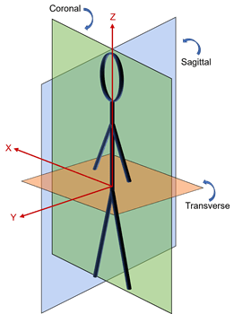
Patient Coordinate System
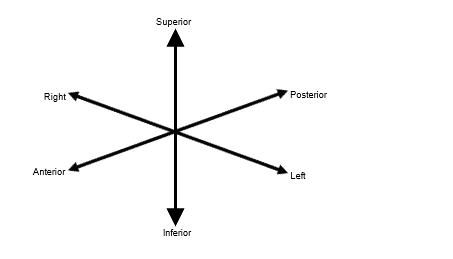
The patient coordinate system is made up of three orthogonal axes:
Left (L)/Right (R) — x-axis
Anterior (A)/Posterior (P) — y-axis
Inferior (I)/Superior (S) — z-axis
The patient xyz-axes define the coronal, sagittal, and transverse anatomical planes. This table shows the relationship between the anatomical planes and patient axes.
| Anatomical Planes and Patient Axes | Sagittal Plane | Coronal Plane | Transverse Plane |
|---|---|---|---|
|
|
|
|
|


Note
The patient coordinate system rotates together with the physical orientation of the patient.
Mapping Patient Coordinate Axes to Anatomical Planes
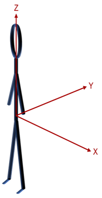
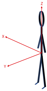
Medical image files store a transformation matrix to map intrinsic coordinates (i, j, k) to patient coordinates (x, y, z), and each file format has a different convention that defines the positive direction of each axis.
For example, a DICOM file uses an LPS+ coordinate system and a NIfTI file uses an RAS+ coordinate system.
| Patient Axes | DICOM | NIfTI |
|---|---|---|
|
|
|
|
|
|
|
Intrinsic Coordinate System
The intrinsic coordinate system describes the spatial dimensions of the patient
coordinate system. Intrinsic coordinates are in units of voxels, while patient coordinates
have real-world dimensions and are usually in units of millimeters. You can obtain pixel
dimensions from the PixelSpacing
property of a medicalImage object for 2-D data, and from the VoxelSpacing
property of a medicalVolume object for 3-D data.
The origin of the intrinsic coordinate system is located at the center of the first pixel (2-D image) or voxel (3-D volume), represented by the black circle. The i-axis corresponds to the first dimension (rows), the j-axis corresponds to the second dimension (columns), and the k-axis corresponds to the third dimension of a medical image or volume.
This image grid shows the i-axis corresponding to the anatomical z-axis and the j-axis corresponding to the anatomical x-axis,
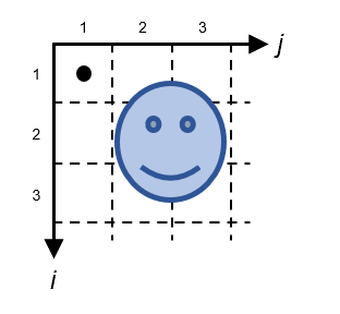
whereas this image grid shows the i-axis corresponding to the anatomical x-axis and the j-axis corresponding to the anatomical z-axis.
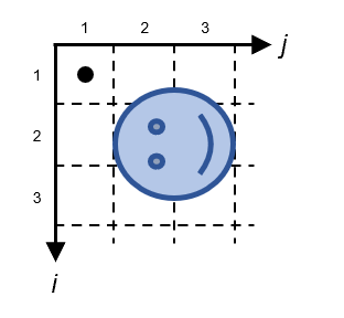
Both image grids represent a valid way a medical device might store voxels in a file.
When you create a medicalVolume object for an image volume, the spatial
dimensions of the patient coordinate system correspond to the values in the
Voxels property of the object.
Tip
Use the intrinsicToWorldMapping function to compute the geometric transformation
between the intrinsic and patient coordinate systems for a medical image volume.