LTE Waveform Modeling Using Downlink Transport and Physical Channels
This example shows how to generate a time-domain waveform containing a physical downlink shared channel, the corresponding physical downlink control channel transmission, and the physical control format indicator channel.
Introduction
This example shows how to generate a complete downlink shared channel (DL-SCH) transmission for six resource blocks and four-antenna transmit diversity. The example models these physical channels:
Physical downlink shared channel (PDSCH)
Physical downlink control channel (PDCCH)
Physical downlink control format indicator channel (PCFICH)
This example generates a time-domain waveform (after OFDM modulation) for all four antenna ports. The example considers a single subframe (number 0).
Cell-Wide Settings
Create a structure to configure the eNodeB settings.
enb.NDLRB = 6;                % No of Downlink Resource Blocks(DL-RB)
enb.CyclicPrefix = 'Normal';  % CP length
enb.PHICHDuration = 'Normal'; % Normal physical HARQ indicator channel (PHICH) duration
enb.DuplexMode = 'FDD';       % FDD duplex mode
enb.CFI = 3;                  % 4 PDCCH symbols
enb.Ng = 'Sixth';             % HICH groups
enb.CellRefP = 4;             % Four antenna ports
enb.NCellID = 10;             % Cell id
enb.NSubframe = 0;            % Subframe number 0
Subframe Resource Grid Generation
Create a resource grid using the lteDLResourceGrid function. This creates an empty resource grid for one subframe. The subframe is represented by a 3D array. The first dimension represents the number of available subcarriers, which is equal to 12*enb.NDLRB because there are 12 subcarriers per resource block. The second dimension represents the number of OFDM symbols in a subframe. The value is 14 in this case, because there are seven OFDM symbols per slot for a normal cyclic prefix length and two slots per subframe. The third dimension represents the number of antenna ports, which is four in this case, as specified in enb.CellRefP.
subframe = lteDLResourceGrid(enb);
DL-SCH and PDSCH Settings
To configure the DL-SCH and PDSCH, create a structure. These settings configure four-antenna transmit diversity with quadrature phase shift keying (QPSK) modulation.
pdsch.NLayers = 4;                       % No of layers
pdsch.TxScheme = 'TxDiversity';          % Transmission scheme
pdsch.Modulation = 'QPSK';               % Modulation scheme
pdsch.RNTI = 1;                          % 16-bit UE-specific mask
pdsch.RV = 0;                            % Redundancy Version
PDSCH Mapping Indices Generation
To generate indices for mapping the complex PDSCH symbols to the subframe resource grid, use the ltePDSCHIndices function. The parameters that this function requires include some of the cell-wide settings in enb, the channel transmission configuration pdsch, and the physical resource blocks (PRBs). The PRBs are the resource allocation for transmission of the PDSCH. This example assumes that all resource blocks are allocated to the PDSCH. This is represented by specifying pdsch.PRBSet as a column vector below.
The example specifies '1based' for direct mapping on the resource grid because MATLAB® uses 1-based indexing. In this case, the example assumes that both slots in the subframe share the same resource allocation. You can set different allocations for each slot by specifying the allocation as a two-column matrix, where each column represents one slot in the subframe.
The resulting matrix pdschIndices has four columns. Each column contains a set of indices in linear style pointing to the resource elements (REs) to be used for the PDSCH in each antenna port. This function returns indices that avoid REs allocated to reference signals, the control region, broadcast channels, and synchronization signals.
The generated indices are represented in 1-based format as used by MATLAB. You can specify standard-compliant 0-based indices using the option '0based'. The default is 1-based.
You can calculate the coded block size for DL-SCH transmission by using the ltePDSCHIndices function. The ltePDSCHIndices function returns an information structure as its second output, which contains the parameter G. G specifies the number of coded and rate-matched DL-SCH data bits to satisfy the physical PDSCH capacity. The example uses this value to parameterize the DL-SCH channel coding.
pdsch.PRBSet = (0:enb.NDLRB-1).';   % Subframe resource allocation
[pdschIndices,pdschInfo] = ...
    ltePDSCHIndices(enb,pdsch,pdsch.PRBSet,'1based');
DL-SCH Channel Coding
The next step is to generate the DL-SCH bits and apply channel coding. This includes CRC calculation, code block segmentation and CRC insertion, turbo coding, rate matching, and code block concatenation. You can perform all of these steps using the lteDLSCH function.
Choose the DL-SCH transport block size according to the rules in TS 36.101, Annex A.2.1.2 [1] "Determination of payload size" with target code rate 1/3 and number of bits per subframe given by codedTrBlkSize.
codedTrBlkSize = pdschInfo.G;                                 % Available PDSCH bits

transportBlkSize = 152;                                       % Transport block size
dlschTransportBlk = randi([0 1],transportBlkSize,1);

% Perform channel coding
codedTrBlock = lteDLSCH(enb, pdsch, codedTrBlkSize, ...
               dlschTransportBlk);
PDSCH Complex Symbols Generation
The example applies these operations to the coded transport block to generate the complex PDSCH symbols:
Scrambling
Modulation
Layer mapping
Precoding
Use the ltePDSCH function to perform these tasks. As well as some of the cell-wide settings specified in enb, this function also requires other parameters related to the modulation and channel transmission configuration, pdsch. The resulting matrix pdschSymbols has four columns. Each column contains the complex symbols to map to each antenna port.
pdschSymbols = ltePDSCH(enb,pdsch,codedTrBlock);
PDSCH Mapping
The locations of the PDSCH symbols in the resource grids are given by pdschIndices. Use the indices to map the symbols to the resource grid.
% Map PDSCH symbols on resource grid
subframe(pdschIndices) = pdschSymbols;
DCI Message Configuration
Downlink control information (DCI) conveys information about the DL-SCH resource allocation, transport format, and information related to the DL-SCH hybrid ARQ. You can use the lteDCI function to generate a DCI message to be mapped to the PDCCH. These parameters include the number of downlink resource blocks, the DCI format, and the resource indication value (RIV). The RIV of 26 corresponds to full bandwidth assignment. The lteDCI function returns a structure and a vector containing the DCI message bits. Both contain the same information. The structure is easier to read, but the serialized DCI message is a more suitable format to send to the channel coding stages.
dci.DCIFormat = 'Format1A';  % DCI message format
dci.Allocation.RIV = 26;     % Resource indication value

[dciMessage, dciMessageBits] = lteDCI(enb,dci); % DCI message
DCI Channel Coding
Channel code the DCI message bits. This includes the following operations:
CRC insertion
Tail-biting convolutional coding
Rate matching
The PDCCHFormat field specifies to use one control channel element (CCE) for the transmission of PDCCH, where a CCE is composed of 36 useful REs.
pdcch.NDLRB = enb.NDLRB;  % Number of DL-RB in total BW
pdcch.RNTI = pdsch.RNTI;  % 16-bit value number
pdcch.PDCCHFormat = 0;    % 1-CCE of aggregation level 1

% Perform DCI message bits coding to form coded DCI bits
codedDciBits = lteDCIEncode(pdcch, dciMessageBits);
PDCCH Bits Generation
The capacity of the control region depends on the bandwidth, the control format indicator (CFI), the number of antenna ports, and the PHICH groups. You can calculate the total number of resources available for PDCCH using the ltePDCCHInfo function. This returns a structure pdcchInfo, where the different fields express the resources available to the PDCCH in different units: bits, CCEs, REs, and resource element groups (REGs). The total number of bits available in the PDCCH region is stored in the pdcchInfo.MTot field. This enables you to build a vector with the appropriate number of elements. Not all the available bits in the PDCCH region are necessarily used. The convention is to set unused bits to -1, while bit locations with values 0 or 1 are used.
This example initializes all elements in pdcchBits to -1. This reflects the fact that, initially, all bits are unused. The elements of codedDciBits are mapped to the appropriate locations in pdcchBits.
Only a subset of all the bits in pdcchBits may be used. These are called the candidate bits. You can calculate their indices using the ltePDCCHSpace function. This returns a two-column matrix. Each row indicates the available candidate locations for the cell-wide settings enb and PDCCH configuration structure pdcch that you provide. The first and second columns contain the indices of the first and last locations respectively of each group of candidates. In this case these indices are 1-based and refer to bits, so you can use them to access locations in pdcchBits. The vector pdcchBits has 664 elements. The 72 bits of codedDciBits are mapped to the chosen candidate in pdcchBits. Therefore, from the 664 elements, 72 take 0 and 1 values, while the rest remain set to -1. The ltePDCCH function interprets these locations as unused and only considers those with 1s and 0s.
pdcchInfo = ltePDCCHInfo(enb);    % Get the total resources for PDCCH
pdcchBits = -1*ones(pdcchInfo.MTot, 1); % Initialized with -1

% Perform search space for UE-specific control channel candidates
candidates = ltePDCCHSpace(enb, pdcch, {'bits','1based'});

% Mapping PDCCH payload on available UE-specific candidate. In this example
% the first available candidate is used to map the coded DCI bits.
pdcchBits( candidates(1, 1) : candidates(1, 2) ) = codedDciBits;
PDCCH Complex Symbol Generation
Generate complex PDCCH symbols from the set of bits used in pdcchBits (values not set to -1). The example performs these operations:
Scrambling
QPSK modulation
Layer mapping
Precoding
The ltePDCCH function takes a set of PDCCH bits and generates complex-valued PDCCH symbols performing the four operations. In this case pdcchSymbols, is a four-column matrix, each corresponding to one antenna port.
pdcchSymbols = ltePDCCH(enb, pdcchBits);
PDCCH Mapping Indices Generation and Resource Grid Mapping
Generate PDCCH indices for symbol mapping on the resource grid. pdcchIndices is a matrix with four columns, one column per antenna port. The rows contain the indices in linear form for mapping the PDCCH symbols to the subframe resource grid.
pdcchIndices = ltePDCCHIndices(enb, {'1based'});

% Map symbols for each antenna port
subframe(pdcchIndices) = pdcchSymbols;
CFI Channel Coding
The number of OFDM symbols in a subframe is linked to the control format indicator (CFI) value. The cell-wide settings structure enb specifies a CFI value of 3, which means that four OFDM symbols are used for the control region in the case of six downlink resource blocks. Channel code the CFI using the lteCFI function. The resulting set of coded bits is a 32-element vector.
cfiBits = lteCFI(enb);
PCFICH Complex Symbol Generation
To create the PCFICH complex symbols, scramble, QPSK-modulate, map to layers, and precode the CFI-coded bits. pcfichSymbols is a matrix with four columns where each column contains the PCFICH complex symbols that map to each of the antenna ports.
pcfichSymbols = ltePCFICH(enb, cfiBits);
PCFICH Indices Generation and Resource Grid Mapping
Map the PCFICH complex symbols to the subframe resource grid using the appropriate mapping indices. Use the ltePCFICHIndices function to generate the indices. Use the indices to map the PCFICH symbol quadruplets to REGs in the first OFDM symbol in a subframe. The process considers all antenna ports and avoids elements used by reference signals. Note that the resulting matrix has four columns; each column contains the indices in linear form for each antenna port. These indices are 1-based, however you can also generate them using 0-based indexing. The resulting matrix contains the complex symbols in pcfichSymbols in the locations specified by pcfichIndices.
pcfichIndices = ltePCFICHIndices(enb);

% Map PCFICH symbols to resource grid
subframe(pcfichIndices) = pcfichSymbols;
Plot Grid
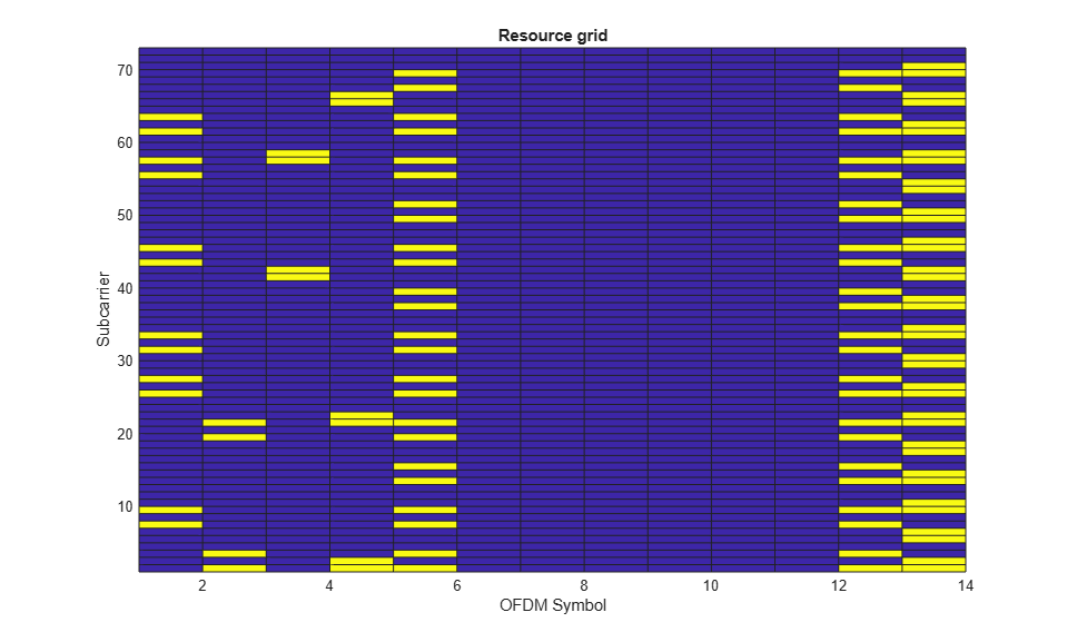
Plot the resource grid for the first antenna. This includes (in yellow) the physical channels added in the example: PDSCH, PDCCH and PCFICH. Use the surf function to avoid aliasing. This plots the values (REs) of the grid and joins them with lines (for 12 subcarriers, surf plots 12 points and 11 lines; thus, the last subcarrier is not visible). Repeat the last row of the resource grid so that the last subcarrier is visible.
surf(abs([subframe(:,:,1);subframe(end,:,1)]));
view(2);
h = rotate3d; setAllowAxesRotate(h,gca,false);
axis tight;
xlabel('OFDM Symbol');
ylabel('Subcarrier');
title('Resource grid');
OFDM Modulation
Map to the time domain by performing OFDM modulation for downlink symbols. The resulting matrix has four columns; each column contains the samples for each antenna port.
[timeDomainMapped,timeDomainInfo] = lteOFDMModulate(enb,subframe);
Selected Bibliography
3GPP TS 36.101 "User Equipment (UE) radio transmission and reception"