Parameterize a Simple Heat Exchanger
This example shows how different fluids and geometries affect the performance of a heat exchanger. This example uses Simscape Fluids heat exchanger blocks and the number of transfer units (NTU) method to calculate heat transfer. For more information on calculating heat transfer by using the log mean temperature difference (LMTD), see EV Battery Cooling System Design or Heat Transfer in a Thermal Liquid Pipe.
This example compares the effectiveness of concentric cylinder, shell and tube, and cross flow heat exchangers. It also explores the effects that different fluids can have on heat transfer.
Define the Heat Transfer Equations
Heat exchangers transfer heat from one fluid to another without mixing the fluids. This example compares concentric cylinder, shell and tube, and cross flow heat exchangers. This example assumes that the heat exchangers are perfectly insulated, and that there is no heat transfer with the outside air. It also does not account for the thermal resistance of any material between the fluids or fouling of the heat exchanger walls.
The heat transfer rate between two fluids in a heat exchanger is
where:
and are the inlet temperatures of fluid 1 and fluid 2.
is the effectiveness parameter, which depends on the heat exchanger attributes and the NTU.
is the minimum thermal capacity rate value, where
and are the mass flow rates of fluid 1 and 2 into the heat exchanger.
and are the specific heat coefficients at constant pressure of fluid 1 and fluid 2.
The number of heat transfer units is
where is the overall heat transfer coefficient. This example does not model the thermal resistance of the heat exchanger walls or account for fouling, so
where:
and are the heat transfer coefficients between fluids 1 and 2 and the interface wall.
and are the heat transfer surface areas for fluids 1 and 2.
This example assumes that the convective heat transfer coefficients are constant. For more information on calculating the heat transfer coefficient, see EV Battery Cooling System Design.
The thermal capacity ratio is
You can use the calculated heat transfer rate to calculate the temperature of the fluid leaving the heat exchanger. The change in temperature is
Because these calculations are the same for all of the heat exchangers in this example, you define the functions to calculate the NTU, thermal capacity ratio, and the heat transfer.
Define a function that uses these equations to calculate the NTU and the thermal capacity ratio.
function [NTU,C_rel] = ntu_thermalcapacity(mdot_1,mdot_2,c_p1,c_p2,R_overall)
    C1 = mdot_1*c_p1;    % [W/k] Heat capacity rate of fluid 1
    C2 = mdot_2*c_p2;    % [W/k] Heat capacity rate of fluid 2
    C_min = min(C1,C2);  % [W/k] Minimum heat capacity rate
    C_max = max(C1,C2);  % [W/k] Maximum heat capacity rate

    C_rel = C_min/C_max; % Thermal capacity ratio
    NTU = 1/(R_overall*C_min);   % Number of transfer units
end
Define a function to calculate the heat transfer and the temperatures of the fluids leaving the heat exchanger. This function assumes that the liquid that enters the heat exchanger on side 1 is colder than the liquid that enters the heat exchanger on side 2.
function [Q,T_1_out,T_2_out] = heattransfer(epsilon,T_1_in,T_2_in,mdot_1,mdot_2,c_p1,c_p2)
    assert(T_1_in < T_2_in, 'Side 2 temperature cooler than side 1')
    C1 = mdot_1*c_p1;    % [W/k] Heat capacity rate of fluid 1
    C2 = mdot_2*c_p2;    % [W/k] Heat capacity rate of fluid 2
    C_min = min(C1,C2);  % [W/k] Minimum heat capacity rate

    Q = abs(epsilon*C_min*(T_2_in-T_1_in));  % [W] Magnitude of heat transfer to fluid 1
    T_1_out = Q/(mdot_1*c_p1)+T_1_in;        % [K] Fluid 1 temperature leaving the heat exchanger
    T_2_out = T_2_in-Q/(mdot_2*c_p2);        % [K] Fluid 2 temperature leaving the heat exchanger
end
Model a Concentric Cylinder Heat Exchanger
Consider a parallel flow concentric cylinder heat exchanger. Hot water flows through the center cylinder, which has a diameter of 0.1 m, and cool water flows through the surrounding cylinder, which has a diameter of 0.2 m. The heat exchanger is 10 m long. Calculate the heat transfer rate and exit temperatures for this heat exchanger.
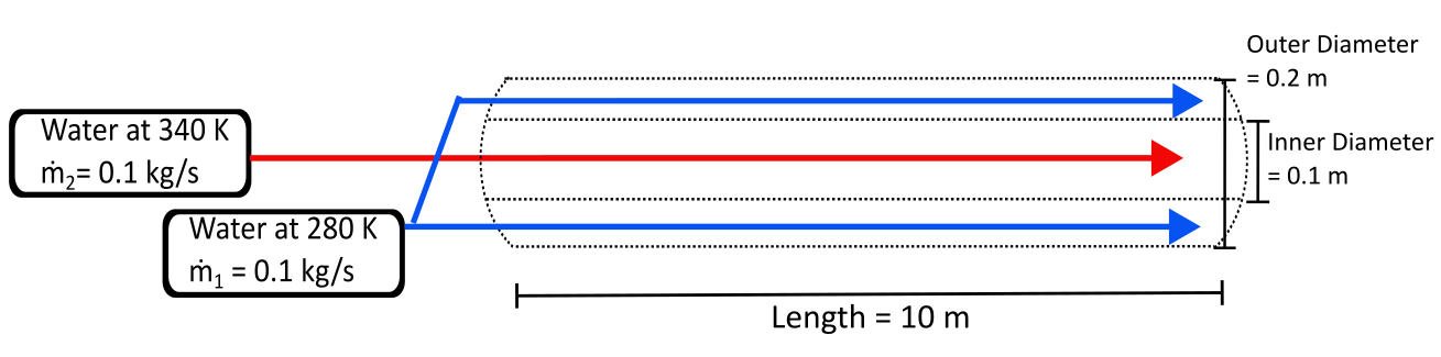
Create MATLAB® variables to represent the heat exchanger size and the temperature, mass flow rate, specific heat, and heat transfer coefficient for both fluids. Fluid 1 is the cold fluid and fluid 2 is the hot fluid.
T_cold_in = 280;    % [K] Cold side inlet temperature
T_hot_in = 340;     % [K] Hot side inlet temperature
L = 10;          % [m] Length
D_inner = 0.1;   % [m] Inner Diameter
D_outer = 0.2;   % [m] Outer Diameter
mdot_1 = 0.1;    % [kg/sec]  Mass flow rate through outer tube
mdot_2 = 0.1;    % [kg/sec]  Mass flow rate through inner tube
c_p1 = 4200;     % [J/(kg*K)] Water specific heat of fluid 1 at atmospheric pressure
c_p2 = 4190;     % [J/(kg*K)] Water specific heat of fluid 2 at atmospheric pressure
h1 = 150;        % [W/(m^2*K)] Heat transfer coefficient for fluid 1
h2 = 150;        % [W/(m^2*K)] Heat transfer coefficient for fluid 2
Calculate the heat transfer surface area, both liquid volumes, and the overall thermal resistance. The heat transfer area is the same for both fluids. Use the function to calculate the NTU and the thermal capacity ratio.
S = L*D_inner*pi;  % [m^2] Heat transfer surface area
V_2 = (D_inner/2)^2*pi*L;      % [m^3] Liquid 2 inner pipe volume
V_1 = (D_outer/2)^2*pi*L-V_2;  % [m^3] Liquid 1 outer pipe volume
R = 1/(S*h1) + 1/(S*h2); % [K/W] Overall thermal resistance

[NTU,C_rel] = ntu_thermalcapacity(mdot_1,mdot_2,c_p1,c_p2,R); % Function call for NTU and C_rel
For a concentric cylinder heat exchanger with parallel flow, the effectiveness is
Calculate the effectiveness and use the function to calculate the heat transfer rate and the temperature of the fluids leaving the heat exchanger.
epsilon = (1-exp(-NTU*(1+C_rel)))/(1+C_rel) % Effectiveness for parallel flow concentric cylinder heat exchangerepsilon = 0.3378
[Q,T_cold_out,T_hot_out] = heattransfer(epsilon,T_cold_in,T_hot_in,mdot_1,mdot_2,c_p1,c_p2) % [Q],[K],[K] Function call for heat transfer rate and final temperaturesQ = 8.4924e+03
T_cold_out =
300.2201
T_hot_out =
319.7317
The heat transfer rate from the inner pipe to the outer pipe is about 8,492 W. The water in the inner tube cools by approximately 20 K over the length of the pipe and the water in the outer pipe warms by about 20 K.
Use the SimpleHeatExchangerParameterizationAndPerformanceTLTL model to confirm these results. The model settings and parameters match the conditions above.
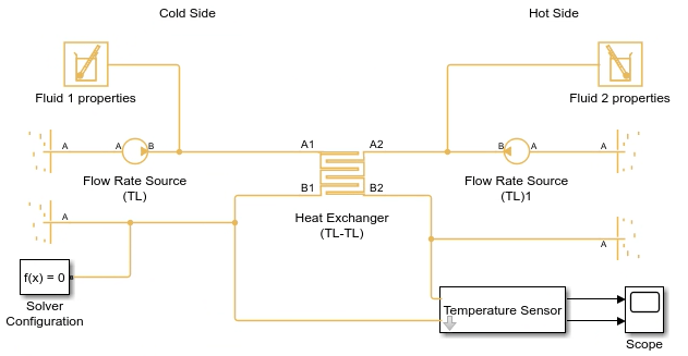
mdl = 'SimpleHeatExchangerParameterizationAndPerformanceTLTL';
open_system(mdl);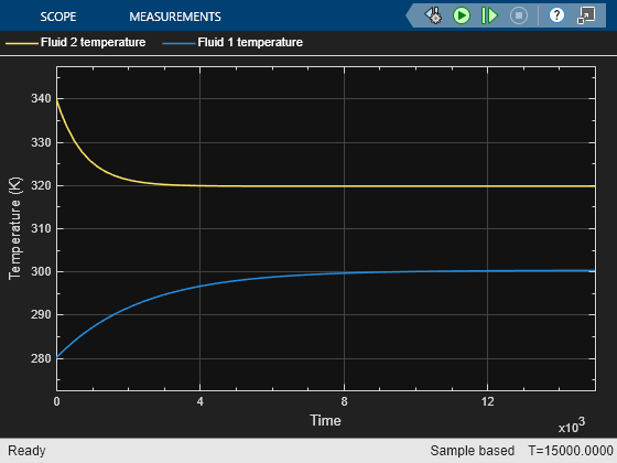
out = sim(mdl);
Q_model = -TLTLlog.Heat_Exchanger_TL_TL.heat_transfer.Q_H1.series.values; % [W] Model heat transfer rate time series
Q_model(end)*1000 % [kW] Model heat transfer rate at end of simulation
ans =
8.4848e+03
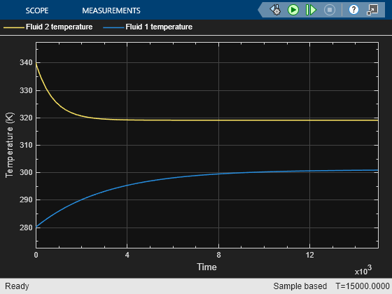
The model results match the analytical results. Both fluids change by about 20 K, although it takes slightly longer for the colder fluid to reach steady state.
Model a Cross Flow Heat Exchanger
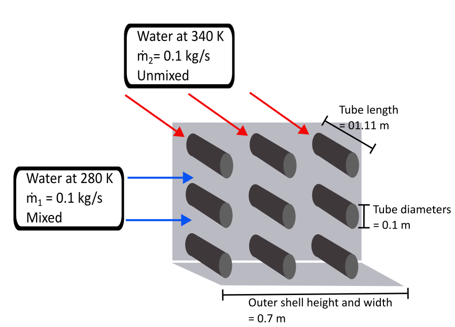
Consider a cross flow heat exchanger where hot water flows through nine circular tubes, each with a diameter of 0.1 m and a length 1.11 m. This length ensures that this heat exchanger has the same heat transfer surface area as the concentric cylinder heat exchanger in the previous section. Cold water flows across the tubes and is mixed. Both fluids have a mass flow rate of 0.1 kg/s. Calculate the heat transfer rate and exit temperatures for this heat exchanger.
Create MATLAB variables to represent the heat exchanger dimensions and calculate the heat transfer surface area, both liquid volumes, and the overall thermal resistance. The heat transfer area is the same for both fluids. Use the function to calculate the NTU and the thermal capacity ratio. Assume that fluid 1 is the cold fluid and fluid 2 is the hot fluid.
L_tube = 10/9; % [m] Length of each tube.
D_tube = 0.1;  % [m] Diameter of each tube
H_shell = 0.7; % [m] Height and width of vessel containing fluid 1
NumTube = 9;   % Number of tube passes in heat exchanger

S_tubes = L_tube*D_tube*pi*NumTube;        % [m^2] Heat transfer surface area
V_tubes = (D_tube/2)^2*pi*L_tube*NumTube;  % [m^3] Liquid in tubes volume
V_shell = H_shell^2*L_tube-V_1;            % [m^3] Liquid in shell volume
R = 1/(S_tubes*h1) + 1/(S_tubes*h2);       % [K/W] Overall thermal resistance
[NTU,C_rel] = ntu_thermalcapacity(mdot_1,mdot_2,c_p1,c_p2,R); % Function call for NTU and C_rel
For a cross flow heat exchanger where the fluid that corresponds to is mixed and the other fluid is unmixed, the effectiveness is
Calculate the effectiveness and use the function to calculate the heat transfer rate and the temperature of the fluids leaving the heat exchanger.
epsilon = (1-exp(-C_rel*(1-exp(-NTU))))/C_rel % Cross flow both effectiveness fluid 1 (C_max) mixed, fluid 2 (C_min) unmixedepsilon = 0.3497
[Q,T_cold_out,T_hot_out] = heattransfer(epsilon,T_cold_in,T_hot_in,mdot_1,mdot_2,c_p1,c_p2) %[Q],[K],[K] Function call for heat transfer rate and final temperaturesQ = 8.7924e+03
T_cold_out =
300.9343
T_hot_out =
319.0157
The heat transfer rate from the fluid in the tubes to the outer fluid is approximately 8,792 W. This heat exchanger is slightly more effective then the concentric cylinder heat exchanger, despite having the same heat transfer surface area. The heat transfer rate and steady state temperatures are nearly the same.
Use the SimpleHeatExchangerParameterizationAndPerformanceTLTL model to confirm these results. Set the parameters in the model to match the conditions for a cross flow heat exchanger where fluid 1 is mixed and fluid 2 is unmixed.
mdl = 'SimpleHeatExchangerParameterizationAndPerformanceTLTL';
open_system(mdl);
set_param('SimpleHeatExchangerParameterizationAndPerformanceTLTL/Heat Exchanger (TL-TL)','hex_type','fluids.heat_exchangers.enum.FlowArrangement.Cross')
set_param('SimpleHeatExchangerParameterizationAndPerformanceTLTL/Heat Exchanger (TL-TL)','cross_type','fluids.heat_exchangers.enum.CrossFlowArrangementTLTL.MixedUnmixed')
set_param('SimpleHeatExchangerParameterizationAndPerformanceTLTL/Heat Exchanger (TL-TL)','heat_transfer_area_1','S_tubes')
set_param('SimpleHeatExchangerParameterizationAndPerformanceTLTL/Heat Exchanger (TL-TL)','heat_transfer_area_2','S_tubes')
set_param('SimpleHeatExchangerParameterizationAndPerformanceTLTL/Heat Exchanger (TL-TL)','liquid_volume_2','V_tubes')
set_param('SimpleHeatExchangerParameterizationAndPerformanceTLTL/Heat Exchanger (TL-TL)','liquid_volume_1','V_shell')
out = sim(mdl);
Q_model = -TLTLlog.Heat_Exchanger_TL_TL.heat_transfer.Q_H1.series.values; % [kW] Model heat transfer rate time series
Q_model(end)*1000 % [W] Model heat transfer rate at end of simulation
ans =
8.7850e+03
These results agree with the analytical solution. In addition to having very similar effectiveness and heat transfer rate, the temperature profiles for the cross flow and concentric cylinder heat exchangers are also very similar. For these heat exchanger parameterizations, there is no performance difference between these two geometries.
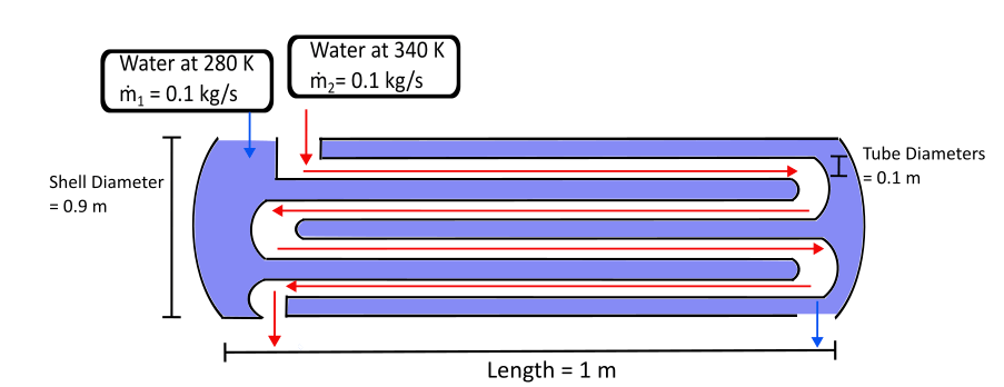
Model a Shell and Tube Heat Exchanger
Consider a shell and tube heat exchanger with four tubes for hot water surrounded by a cylindrical shell filled with cold water. The outer shell and the tubes are 1 m long. The diameter of each of the tubes is 0.1 cm. Cold water can flow freely around the tubes, but it follows the same flow direction as the hot water. Calculate the heat transfer rate and exit temperatures for this heat exchanger.
Create MATLAB variables to represent the heat exchanger size and dimensions.
L_tube = 1;    % [m] Length of each tube
D_tube = 0.1;  % [m] Diameter of each tube
D_shell = 0.9; % [m] Diameter of outer shell
NumPass = 4; % Number of tube passes in heat exchanger
Calculate the heat transfer surface area, both liquid volumes, and the overall thermal resistance. The heat transfer area is the same for both fluids. Use the function to calculate the NTU and the thermal capacity ratio.
S_tubes = L_tube*D_tube*pi*NumPass;    % [m^2] Heat transfer surface area
V_tubes = (D_tube/2)^2*pi*L_tube*NumPass;  % [m^3] Liquid in tubes volume
V_shell = (D_shell/2)^2*pi*L_tube-V_1;     % [m^3] Liquid in shell volume
R = 1/(S_tubes*h1) + 1/(S_tubes*h2);   % [K/W] Overall thermal resistance
[NTU,C_rel] = ntu_thermalcapacity(mdot_1,mdot_2,c_p1,c_p2,R); % Function call for NTU and C_rel
For a shell and tube heat exchanger, the effectiveness is
where
Calculate the effectiveness and use the function to calculate the heat transfer rate and the temperature of the fluids leaving the heat exchanger.
epsilon_1 = 2/(1+C_rel+sqrt(1+C_rel^2)*(1+exp(-NTU*sqrt(1+C_rel^2)))/(1-exp(-NTU*sqrt(1+C_rel^2)))); % Intermediate value used to calculate effectiveness
epsilon = (((1-epsilon_1*C_rel)/(1-epsilon_1))^NumPass-1)/(((1-epsilon_1*C_rel)/(1-epsilon_1))^NumPass-C_rel)        % Shell and tube effectiveness
epsilon =
0.4718
[Q,T_cold_out,T_hot_out] = heattransfer(epsilon,T_cold_in,T_hot_in,mdot_1,mdot_2,c_p1,c_p2) %[Q],[K],[K] Function call for heat transfer rate and final temperaturesQ = 1.1861e+04
T_cold_out =
308.2401
T_hot_out =
311.6925
The heat transfer rate from the fluid in the tubes to the fluid in the outer shell is about 11,861 W. The shell and tube heat transfer is much more effective than the previous two heat exchangers, despite the fact that the surface area is almost a third smaller. It has a heat transfer surface area of only 1.25 m^2, while the previous heat exchangers have a surface area of 3.14 m^2.
Use the SimpleHeatExchangerParameterizationAndPerformanceTLTL model to confirm these results. Set the parameters in the model to match the conditions for the shell and tube heat exchanger.
mdl = 'SimpleHeatExchangerParameterizationAndPerformanceTLTL';
open_system(mdl);
set_param('SimpleHeatExchangerParameterizationAndPerformanceTLTL/Heat Exchanger (TL-TL)','hex_type','fluids.heat_exchangers.enum.FlowArrangement.ShellTube')
set_param('SimpleHeatExchangerParameterizationAndPerformanceTLTL/Heat Exchanger (TL-TL)','shell_num','NumPass')
set_param('SimpleHeatExchangerParameterizationAndPerformanceTLTL/Heat Exchanger (TL-TL)','heat_transfer_area_1','S_tubes')
set_param('SimpleHeatExchangerParameterizationAndPerformanceTLTL/Heat Exchanger (TL-TL)','heat_transfer_area_2','S_tubes')
set_param('SimpleHeatExchangerParameterizationAndPerformanceTLTL/Heat Exchanger (TL-TL)','liquid_volume_2','V_tubes')
set_param('SimpleHeatExchangerParameterizationAndPerformanceTLTL/Heat Exchanger (TL-TL)','liquid_volume_1','V_shell')
out = sim(mdl);
Q_model = -TLTLlog.Heat_Exchanger_TL_TL.heat_transfer.Q_H1.series.values; % [kW] Model heat transfer rate time series
Q_model(end)*1000 % [W] Model heat transfer rate at end of simulation
ans =
1.1853e+04
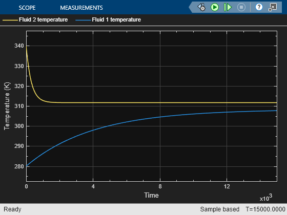
These results match the analytical solution. Both fluid temperatures change much more, by almost 30 K, because of the effectiveness of the shell and tube exchanger. Additionally, the rate of the temperature change before the fluids reach steady state is faster, especially for fluid 1.
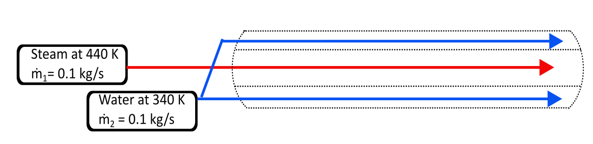
Model Heat Transfer Between Different Fluids
The type of fluid in the heat exchanger also impacts the heat transfer rate and final temperatures. Consider the previous parallel flow concentric cylinder heat exchanger, but instead of hot water, steam at 440 K flows through the inner cylinder and water at 340 K flows in the outer cylinder. Ignore any effects of fluid phase changes and assume that the steam behaves as a perfect gas. Calculate the heat transfer rate and exit temperatures for this heat exchanger.
Create MATLAB variables to represent the heat exchanger size and the temperature, specific heat, and heat transfer coefficient for both steam. Calculate both liquid volumes, the overall thermal resistance, and the NTU and the thermal capacity ratio.
T_steam_in = 440;    % [K] Steam temperature
c_psteam = 2027;  % [J/(kg*K)] Specific heat of steam
h_steam = 2500;   % [W/(m^2*K)] Heat transfer coefficient for steam

V_2 = (D/2)^2*pi*L;  % [m^3] Liquid 2 volume
V_1 = D^2*pi*L-V_2;  % [m^3] Liquid 1 volume
R = 1/(S*h2) + 1/(S*h_steam); % [K/W] Overall thermal resistance
[NTU,C_rel] = ntu_thermalcapacity(mdot_1,mdot_2,c_p2,c_psteam,R); % Function call for NTU and C_rel
Calculate the effectiveness and use the function to calculate the heat transfer rate and the temperature of the fluids leaving the heat exchanger.
epsilon = (1-exp(-NTU*(1+C_rel)))/(1+C_rel); % Effectiveness for parallel flow concentric cylinder heat exchanger
[Q,T_cold_out,T_steam_out] = heattransfer(epsilon,T_hot_in,T_steam_in,mdot_1,mdot_2,c_p2,c_psteam) %[Q],[K],[K] Function call for heat transfer rate and final temperatures
Q =
1.3134e+04
T_cold_out =
371.3453
T_steam_out =
375.2063
Use the SimpleHeatExchangerParameterizationAndPerformanceTLGas model to confirm these results.
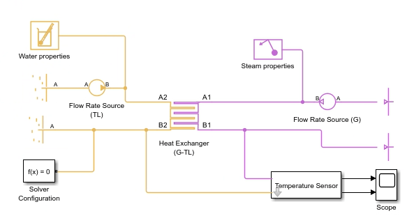
mdl = 'SimpleHeatExchangerParameterizationAndPerformanceTLGas';
open_system(mdl);
out = sim(mdl);
Q_model = TLGlog.Heat_Exchanger_G_TL.heat_transfer.Q_H1.series.values; % [kW] Model heat transfer rate time series
Q_model(end)*1000 % [W] Model heat transfer rate
ans =
1.3035e+04
The steam reaches its steady state temperature much faster than the water does. When you view the steam temperature on the same time scale as the water temperature, you cannot see the initial dynamics. Plot the first several seconds of the steam temperature with respect to time.
temp_steam = TLGlog.Heat_Exchanger_G_TL.B1.T.series.values; % [K] Model heat transfer rate time series
plot(out(1:125),temp_steam(1:125))
xlabel('Time (s)')
ylabel('Temperature (K)')
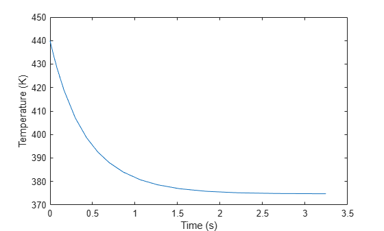
The steam changes temperature much faster because it has a lower specific heat capacity, which means it lakes less energy to change the temperature. Steam has a lower specific heat capacity because the intermolecular forces in steam are weaker than in water. Fluids that are effective for heat transfer, such as water, ethylene glycol, and propylene glycol mixed with water, have specific heat capacities around 4,000 J/(kg*K), which means they can absorb a large amount of heat without significantly changing temperature. The results demonstrate this behavior, because the steam temperature drops by approximately 65 K while the water temperature only increases by approximately 30 K.
References
[1] Adrienne S. Lavine, Frank P. Incropera, David P. DeWitt, Theodore L. Bergman. Fundamentals of heat and mass transfer. Vol. 6. New York: Wiley, 1996.