Main Content

Rotating Single-Acting Actuator (IL)

Actuator on a rotating shaft in an isothermal liquid network

Since R2020a

  • Rotating Single-Acting Actuator (IL) block

Libraries:
Simscape / Fluids / Isothermal Liquid / Actuators

Description

The Rotating Single-Acting Actuator (IL) block models an actuator that rotates around its central axis in an isothermal liquid network. Rotating actuators are used in rotating shaft control components such as friction clutches or brakes. The fluid enters the actuator at port A. The angular velocity is set at port W. Port C is associated with the actuator casing and the piston velocity and force are set at port R.

When the piston position is calculated internally, it is reported at port p, and when the position is set by a connection to a Simscape™ Multibody™ joint, it is received as a physical signal at port p. The motion of the piston when it is near full extension or full retraction is limited by one of four hard stop models. Fluid dynamic compressibility can optionally be modeled.

Displacement

The piston displacement is measured as the position at port R relative to port C. The Mechanical orientation identifies the direction of piston displacement. The piston displacement is neutral, or 0, when the chamber volume is equal to the Dead volume. When displacement is received as an input, ensure that the derivative of the position is equal to the piston velocity. This is automatically the case when the input is received from a Translational Multibody Interface block connection to a Simscape Multibody joint.

Hard Stop Model

To avoid mechanical damage to an actuator when it is fully extended or fully retracted, an actuator typically displays nonlinear behavior when the piston approaches these limits. The Double-Acting Actuator (IL) block models this behavior with a choice of four hard stop models, which model the material compliance through a spring-damper system. The hard stop models are:

  • Stiffness and damping applied smoothly through transition region, damped rebound.

  • Full stiffness and damping applied at bounds, undamped rebound.

  • Full stiffness and damping applied at bounds, damped rebound.

  • Based on coefficient of restitution

The hard stop force is modeled when the piston is at its upper or lower bound. The boundary region is within the Transition region of the Piston stroke or piston initial displacement. Outside of this region, FHardStop=0.

For more information about these settings, see the Translational Hard Stop block page.
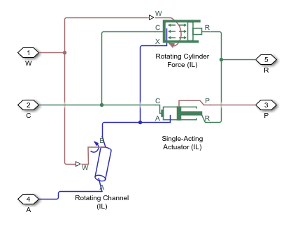
Block Subcomponents

The Rotating Single-Acting Actuator (IL) block comprises three Isothermal Liquid library blocks:

Actuator Schematic

Ports

Conserving

expand all

Inlet port to the liquid chamber.

Reference port for actuator velocity and force.

Port associated with the piston velocity and force.

Input

expand all

Actuator rotational velocity, received as a physical signal in rad/s.

Piston position in m, received as a physical signal from a Simscape Multibody block.

Dependencies

To expose this port, set Piston displacement to Provide input signal from Multibody joint.

Output

expand all

Piston position in m, returned as a physical signal.

Dependencies

To expose this port, set Piston displacement to Calculate from velocity of port R relative to port C.

Parameters

expand all

Actuator

Piston outer radius.

Piston inner radius.

Sets the piston displacement direction. When you set this parameter to:

  • Pressure at A causes positive displacement of R relative to C the piston displacement is positive when the volume of liquid at port A is expanding. This corresponds to rod extension.

  • Pressure at A causes negative displacement of R relative to C the piston displacement is negative when the volume of liquid at port A is expanding. This corresponds to rod contraction.

Maximum piston travel distance.

Volume of liquid when the piston displacement is 0. This is the liquid volume when the piston is up against the actuator end cap.

Environment reference pressure. The Atmospheric pressure option sets the environmental pressure to 0.101325 MPa.

User-defined environmental pressure.

Dependencies

To enable this parameter, set Environment pressure specification to Specified pressure.

Fluid Channel

Radius of the fluid opening in the rotating shaft. This value must be greater than or equal to the Piston inner radius and less than or equal to the Piston outer radius.

Cross-sectional area of the fluid channel.

Flow discharge loss coefficient.

Upper Reynolds number limit for laminar flow through the orifice.

Hard Stop

Model choice for the force on the piston at full extension or full retraction. See the Translational Hard Stop block for more information.

Piston stiffness coefficient.

Dependencies

To enable this parameter, set Hard stop model to

  • Stiffness and damping applied smoothly through transition region, damped rebound

  • Full stiffness and damping applied at bounds, undamped rebound

  • Full stiffness and damping applied at bounds, damped rebound

Piston damping coefficient.

Dependencies

To enable this parameter, set Hard stop model to

  • Stiffness and damping applied smoothly through transition region, damped rebound

  • Full stiffness and damping applied at bounds, undamped rebound

  • Full stiffness and damping applied at bounds, damped rebound

Application range of the hard stop force model. Outside of this range of the piston maximum extension and piston maximum retraction, the Hard stop model is not applied and there is no additional force on the piston.

Dependencies

To enable this parameter, set Hard stop model to Stiffness and damping applied smoothly through transition region, damped rebound.

Ratio of the final to the initial relative speed between the slider and the stop after the slider bounces.

Dependencies

To enable this parameter, set Hard stop model to Based on coefficient of restitution.

Threshold relative speed between slider and stop before collision. When the slider hits the case with speed less than the value of the Static contact speed threshold parameter, they stay in contact. Otherwise, the slider bounces. To avoid modeling static contact between the slider and the case, set this parameter to 0.

Dependencies

To enable this parameter, set Hard stop model to Based on coefficient of restitution.

Minimum force needed to release the slider from a static contact mode.

Dependencies

To enable this parameter, set Hard stop model to Based on coefficient of restitution.

Initial Conditions

Method for determining the piston position. The block can receive the position from a Multibody block when set to Provide input signal from Multibody joint, or calculates the position internally and reports the position at port p. The position is between 0 and the Piston stroke when the mechanical orientation is positive and 0 and –Piston stroke when the mechanical orientation is negative.

Piston position at the start of the simulation.

Dependencies

To enable this parameter, set Piston displacement to Calculate from velocity of port R relative to port C.

Whether to model any change in fluid density due to fluid compressibility. When you select Fluid dynamic compressibility, changes due to the mass flow rate into the block are calculated in addition to density changes due to changes in pressure. In the Isothermal Liquid Library, all blocks calculate density as a function of pressure.

Starting liquid pressure for compressible fluids.

Dependencies

To enable this parameter, select Fluid dynamic compressibility.

Extended Capabilities

C/C++ Code Generation
Generate C and C++ code using Simulink® Coder™.

Version History

Introduced in R2020a

expand all