Main Content

Cartridge Valve Insert (IL)

Cartridge flow-control valve in an isothermal liquid network

Since R2020a

  • Cartridge Valve Insert (IL) block

Libraries:
Simscape / Fluids / Isothermal Liquid / Valves & Orifices / Flow Control Valves

Description

The Cartridge Valve Insert (IL) block models a cartridge flow-control valve in an isothermal liquid network. The valve seat can be specified as conical or as a custom opening parameterized by analytical or tabular formulations. The valve opens when the combined pressures at ports A and B exceed the Spring preload force and pressure at port X.

You can specify the block seat geometry as either conical or a custom. This seat setting determines the sub-components that make up the block. In both configurations, the Port A poppet to port X pilot area ratio parameter sets the force ratio in the underlying Cartridge Valve Actuator block.

Use the Cartridge Valve Insert (IL) block when you would like flow control set by a pilot pressure line. Use the Pressure-Compensated 3-Way Flow Control Valve (IL) or Pressure-Compensated Flow Control Valve (IL) block for flow control due to a pressure differential or the Poppet Valve (IL) block for valve opening controlled by an external physical signal.

Conical Valve Seat

The conical cartridge valve insert is a composite of two Isothermal Liquid library blocks:

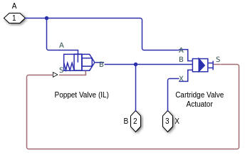
Conical Cartridge Valve Insert Schematic

Custom Valve Seat

The custom cartridge valve insert is a composite of two Isothermal Liquid library blocks:

Custom Cartridge Valve Insert Schematic

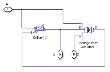
In the custom configuration, you can parameterize the valve opening analytically or with a data set.

Analytical Parameterization

By setting Orifice parameterization to Linear - area vs. control member position, the valve opening area is linearly proportional to the poppet position. Once the pressure at port A or B exceeds the Spring preload force, the valve opens until the Maximum orifice area is reached. When the valve is fully closed, a small Leakage area remains open to flow so that numerical continuity is maintained in the network.

Tabulated Parameterization

By setting Orifice parameterization to Tabulated data - Area vs. control member position, you can supply the opening profile based on opening area and poppet position. The block queries between data points with linear interpolation and uses nearest extrapolation for points beyond the table boundaries.

By setting Orifice parameterization to Tabulated data - Volumetric flow rate vs. control member position and pressure drop, you can supply the volumetric flow rate through the valve as a parameterized table of poppet position and valve pressure drop. The block queries between data points with linear interpolation and uses linear extrapolation for points beyond the table boundaries. The volumetric flow rate is converted to a mass flow rate by multiplying by the fluid density.

Opening Dynamics

If opening dynamics are modeled, a lag is introduced to the flow response to the modeled control pressure. pcontrol becomes the dynamic control pressure, pdyn; otherwise, pcontrol is the steady-state pressure. The instantaneous change in dynamic control pressure is calculated based on the Opening time constant, τ:

p˙dyn=pcontrolpdynτ.

By default, Opening dynamics is set to Off.

Numerically-Smoothed Force and Opening

When the actuator is close to full extension or full retraction, and Orifice parameterization is set to Linear - area vs. control member position, you can maintain numerical robustness in your simulation by adjusting the block Smoothing factor. A smoothing function is applied to the actuator force and orifice opening or area, but primarily influences the simulation at the extremes of these ranges.

The normalized force that opens the valve is

F^=FA+FBFPreloadFPilotkxstroke.

where:

  • FA is the force at port A.

  • FB is the force at port B.

  • FPreload is the Spring preload force.

  • FPilot is the force at port X.

When Valve seat specification is set to Conical, the block smoothly saturates the orifice opening distance between 0 and the maximum orifice opening distance. When Valve seat specification is set to Custom, the block smoothly saturates the valve opening area between the Leakage area parameter and the Maximum orifice area parameter.

For more information, see Numerical Smoothing.

Ports

Conserving

expand all

Liquid entry or exit port.

Liquid entry or exit port.

Pilot pressure port. There is no mass flow rate through port X.

Parameters

expand all

Geometry of valve seat. This parameter is used for calculating the open area between the poppet and seat.

Diameter of the valve control member.

Dependencies

To enable this parameter, set Valve seat specification to Conical.

Angle of the seat opening.

Dependencies

To enable this parameter, set Valve seat specification to Conical.

The valve opening is calculated in one of three ways, linearly or by tabulated data:

  • Linear - area vs. control member position: The orifice area is determined by a linear relationship to the poppet opening or closing distance.

  • Tabulated data - Area vs. control member position: The opening area is interpolated from the Poppet position vector and the Orifice area vector based on the current poppet position.

  • Tabulated data - Volumetric flow rate vs. control member position and pressure drop. The volumetric flow rate is directly interpolated from the provided Poppet position vector, s; Pressure drop vector, dp; and Volumetric flow rate table, q(s,dp) parameters, based on the current poppet position.

Dependencies

To enable this parameter, set Valve seat specification to Custom.

Maximum poppet extension.

Dependencies

To enable this parameter, set Valve seat specification to Custom and Orifice parameterization to Linear - area vs. control member position.

Cross-sectional area of the orifice in its fully open position. This parameter is used as an upper limit for area-pressure calculations during the simulation.

Dependencies

To enable this parameter, set Valve seat specification to Custom and Orifice parameterization to Linear - area vs. control member position.

Vector of orifice opening positions for the tabular parameterization of the orifice opening area. The vector elements must correspond one-to-one with the elements in the Orifice area vector parameter. The elements are listed in ascending order and must be greater than 0.

Dependencies

To enable this parameter, set Valve seat specification to Custom and Orifice parameterization to Tabulated data - Area vs. control member position.

Vector of valve opening areas for the tabular parameterization of the valve opening area. The vector elements must correspond one-to-one with the elements in the Poppet position vector parameter. The elements are listed in ascending order and must be greater than 0.

Dependencies

To enable this parameter, set Valve seat specification to Custom and Orifice parameterization to Tabulated data - Area vs. control member position.

Vector of control member positions for the tabular parameterization of the volumetric flow rate. The spool travel vector forms an independent axis with the Pressure drop vector, dp parameter for the 3-D dependent Volumetric flow rate table, q(s,dp) parameter. A positive displacement corresponds to valve opening. The values are listed in ascending order and the first element must be 0. Linear interpolation is employed between table data points.

Dependencies

To enable this parameter, set Valve seat specification to Custom and Orifice parameterization to Volumetric flow rate vs. control member position and pressure drop.

Vector of pressure drop values for tabular parametrization of volumetric flow rate. The pressure drop vector forms an independent axis with the Poppet position vector, s parameter for the 3-D dependent Volumetric flow rate table, q(s,dp) parameter. The values are listed in ascending order and must be greater than 0. Linear interpolation is employed between table data points.

Dependencies

To enable this parameter, set Valve seat specification to Custom and Orifice parameterization to Volumetric flow rate vs. control member position and pressure drop.

Matrix of volumetric flow rates based on independent values of pressure drop and spool travel distance. M and N are the sizes of the corresponding vectors:

  • M is the number of elements in the Poppet position vector, s parameter.

  • N is the number of elements in the Pressure drop vector, dp parameter.

Dependencies

To enable this parameter, set Valve seat specification to Custom and Orifice parameterization to Volumetric flow rate vs. control member position and pressure drop.

Cross-sectional area of port A.

Ratio of the inlet port, A, to the pilot pressure port, X. This value is used to calculate the force at port X. The ratio must be less than or equal to 1.

Spring force on the poppet when the poppet is in the neutral position. This parameter is a threshold value which, when added to the pilot pressure at port X, counterbalances the valve opening due to the pressures at ports A and B.

Spring stiffness constant.

Sum of all gaps when the valve is in the fully closed position. Any area smaller than this value is saturated to the specified leakage area. This contributes to numerical stability by maintaining continuity in the flow.

Dependencies

To enable this parameter, set either:

  • Valve seat specification to Conical.

  • Valve seat specification to Custom and Orifice parameterization to Linear - Area vs. control member position.

Correction factor that accounts for discharge losses in theoretical flows.

Dependencies

To enable this parameter, set either:

  • Valve seat specification to Conical.

  • Valve seat specification to Custom and Orifice parameterization to Linear - Area vs. control member position or Tabulated data - Area vs. control member position.

Upper Reynolds number limit for laminar flow through the valve.

Dependencies

To enable this parameter, set either:

  • Valve seat specification to Conical.

  • Valve seat specification to Custom and Orifice parameterization to Linear - Area vs. control member position or Tabulated data - Area vs. control member position.

Continuous smoothing factor that introduces a layer of gradual change to the flow response when the valve is in near-open or near-closed positions. Set this value to a nonzero value less than one to increase the stability of your simulation in these regimes.

Dependencies

To enable this parameter, set either:

  • Valve seat specification to Conical.

  • Valve seat specification to Custom and Orifice parameterization to Linear - Area vs. control member position.

Constant that captures the time required for the fluid to reach steady-state conditions when opening or closing the valve from one position to another. This parameter impacts the modeled opening dynamics.

Extended Capabilities

C/C++ Code Generation
Generate C and C++ code using Simulink® Coder™.

Version History

Introduced in R2020a