Generate IP Core with Multiple AXI4-Stream Channels
This example shows how to model an audio system with multiple AXI4-Stream channels and deploy it on a ZedBoard™ by using an audio reference design.
Introduction
In this example, you model a programmable audio filter with spectrogram using multiple AXI4-Stream channels and advanced AXI4-Stream signals Ready and TLAST. One AXI4-Stream channel transfers data between the filter and the audio codec. The other AXI4-Stream channel interfaces with the Processing System to program filter coefficients and transmit spectrogram data to the host computer for analysis.
You can then run the IP Core Generation workflow to generate an HDL IP core and deploy the algorithm on a ZedBoard by using an audio reference design.
System Architecture
This figure shows the high-level architecture of the system.
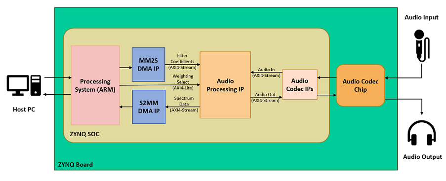
The Audio Codec IPs configure the audio codec and transfer audio data between the ZedBoard and audio codec. The Audio Processing IP generated by HDL Coder™ performs filtering and spectrum analysis. The DMA IPs transfer AXI4-Stream data between the Processing System and the FPGA. The stream data transmitted from the Processing System through the MM2S DMA IP programs the filter coefficients on the FPGA. The stream data received by the Processing System through the S2MM DMA IP contains the spectrogram data computed on the FPGA. The Processing System also configures the weighting curve for spectrum analysis using an AXI4-Lite interface.
Prerequisites
This example extends the audio filter on live input example to use multiple streaming channels. To learn about the example that uses a single streaming channel, see Implement an Audio Filter on a Zynq Board.
To run this example, you must have the following software and hardware installed and set up:
HDL Coder Support Package for AMD® FPGA and SoC Devices
Embedded Coder® Support Package for AMD® SoC Devices
Vivado® Design Suite latest version, as mentioned in HDL Language Support and Supported Third-Party Tools and Hardware
ZedBoard
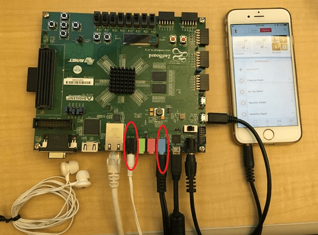
To setup the ZedBoard, refer to the Set up Zynq hardware and tools section in the Get Started with IP Core Generation from Simulink Model example. Connect an audio input from a mobile or an MP3 player to the LINE IN jack and either earphones or speakers to the HPH OUT jack on the ZedBoard as shown below.
Model Audio Processing Algorithm
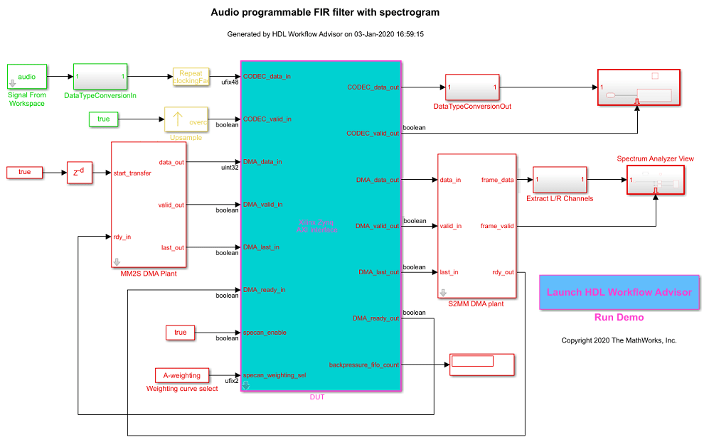
Open the model hdlcoder_audio_filter_multistream.
open_system('hdlcoder_audio_filter_multistream')
set_param('hdlcoder_audio_filter_multistream', 'SimulationCommand', 'Update')
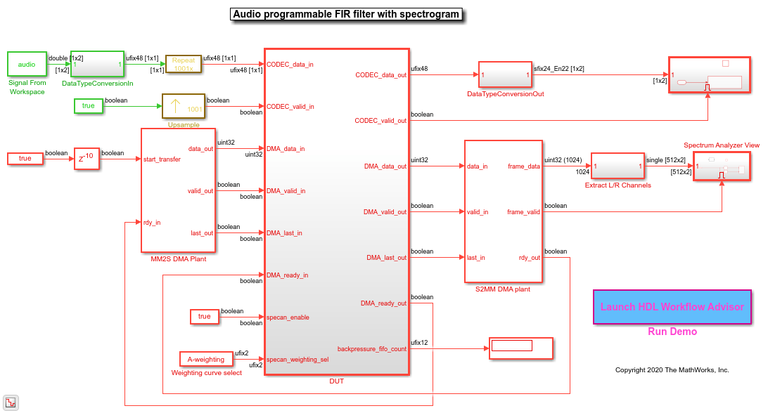
The model contains the DUT subsystem for audio processing, source and sink blocks for simulating the audio, and plant models for DMAs that transfer stream data between the Processing System and FPGA.
Rate Considerations
For audio applications running on the FPGA, the FPGA clock rate is several times faster than the audio sample rate. The ratio of the FPGA clock rate to the audio data sample rate is the Oversampling factor. In this example, the Oversampling factor is modeled by using Repeat and Upsample blocks.
Modeling your design at the FPGA clock rate allows you to optimize resource usage on the target hardware platform by leveraging idle clock cycles and reusing various components. The audio application illustrated in this example uses an audio sample rate of 48kHz and an FPGA clock rate of 96MHz. The Oversampling factor in this case is 2000. Such a large value of Oversampling factor slows down the Simulink® simulation significantly.
To reduce the simulation time, instead of using the Oversampling factor setting, you can model your design at the minimum Oversampling factor that is required by the design. The minimum required Oversampling factor for the design can be determined by the length of the audio filter, which is 1001. This value reduces the simulation time by half and provides sufficient idle cycles between the data samples for the serial filter logic.
Audio Filter
Inside the DUT subsystem, the FIR filter processes data from the audio codec AXI4-Stream channel. The filter coefficients are generated in MATLAB® and programmed by using the second AXI4-Stream interface that interfaces with the Processing System. The filtered audio output is streamed back to the audio codec.
The audio filter is a fully serial implementation of an FIR filter. This filter structure is best suited for audio applications that require large Oversampling factor because the filter uses a multiply accumulate (MAC) operation for each channel. The filter also uses RAM blocks to implement the data delay line and the coefficient source. This implementation saves area by avoiding the high slice logic usage of high-order filters.
Spectrum Analyzer
The audio signal is fed into a spectrum analyzer after passing through the FIR filter. The spectrum analyzer computes the FFT of the filtered signal, applies a weighting function, and converts the result to dBm. You can program the type of weighting to be performed by using the AXI4-Lite interface as either No-weighting, A-weighting, C-weighting, or K-weighting. The actual weighting functions are implemented using lookup tables that have been generated by using Audio Toolbox™ function weightingFilter.
Model AXI4-Stream Interfaces
The model contains two AXI4-Stream interfaces. One AXI4-Stream interface communicates with the audio codec. The other AXI4-Stream interface communicates with the Processing System through the DMAs. The audio codec interface only requires the Data and Valid signals. The DMA interface, on the other hand, additionally uses the Ready and TLAST signals of the AXI4-Stream protocol.
To learn more about the signals used in AXI4-Stream modeling, see Model Design for AXI4-Stream Interface Generation.
Ready Signal
In an AXI4-Stream interface, you use the Ready signal to apply or respond to back pressure. The model uses the Ready signal on the AXI4-Stream Master channel from the FPGA to the Processing System to respond to back pressure from the DMA. When the downstream DMA cannot receive more spectrogram samples, it de-asserts the input Ready signal on the AXI4-Stream Master channel. To ensure that the spectrogram samples are not dropped, the model buffers the data in a FIFO until the Ready signal is asserted, indicating that the DMA is ready to receive samples again.
The AXI4-Stream Slave channel from the Processing System to the FPGA does not have to apply back pressure, and hence its Ready signal is always asserted. The audio codec does not process back pressure and does not use its Ready signal on either channel. To learn more about the Ready signal in AXI4-Stream modeling, see Ready Signal (Optional).
TLAST Signal
The TLAST signal is used to indicate the last sample of a frame. The model uses the TLAST signal on the AXI4-Stream Slave channel as an indicator that it has received a full set of filter coefficients. On the AXI4-Stream Master channel, the TLAST signal is used to indicate the end of a spectrum analyzer frame. To learn more about the TLAST signal in AXI4-Stream modeling, see TLAST Signal (optional).
Customize the Model for ZedBoard
To implement this model on the ZedBoard, you must first have a reference design in Vivado that receives audio input on the ZedBoard and transmits the processed audio data out of the ZedBoard. For details on how to create a reference design which interfaces with the audio codec on the ZedBoard, see Build Custom Reference Design to Interface with Peripheral Chip. This example extends the reference design in that example by adding DMA IPs for communication with the Processing System.
In the reference design, left and right channel audio data are combined to form a single channel such that the lower 24 bits form the left channel and upper 24 bits form the right channel. In the Simulink model shown above, CODEC_data_in is split into left and right channels. Filtering is done on each channel individually. The channels are then concatenated to form a single channel for CODEC_data_out.
Generate HDL IP Core with AXI4-Stream Interfaces
Next, you can start the HDL Workflow Advisor and use the Zynq hardware-software co-design workflow to deploy this design on the Zynq hardware. For a more detailed step-by-step guide, you can refer to the Getting Started with HW/SW Co-design Workflow for Xilinx Zynq Platform example.
1. Set up the Vivado synthesis tool path using the hdlsetuptoolpath command in the MATLAB command window. Use your own Vivado installation path when you run the command.
hdlsetuptoolpath('ToolName', 'Xilinx Vivado', ...
        'ToolPath', vivadopath);
2. Add both the IP repository folder and the ZedBoard registration file to the MATLAB path using following commands:
example_root = (hdlcoder_amd_examples_root)
cd (example_root)
addpath(genpath('ipcore'));
addpath(genpath('ZedBoard'));
3. Open the HDL Workflow Advisor from the DUT subsystem, hdlcoder_audio_filter_multistream/DUT or double-click the Launch HDL Workflow Advisor box in the model.
The target interface settings are already saved for ZedBoard in this example model, so the settings in tasks 1.1 to 1.3 are automatically loaded. To learn more about saving target interface settings in the model, you can refer to the Save Target Hardware Settings in Model example.
4. Run the Set Target Device and Synthesis Tool task.
In this task, IP Core Generation is selected for Target workflow, and ZedBoard is selected for Target platform.
5. Run the Set Target Reference Design task. Audio system with DMA Interface is selected as the Reference Design.
6. Run the Set Target Interface task.
In this task, the ports of the DUT subsystem are mapped to the IP Core interfaces. The audio codec ports are mapped to the Audio Interface and the DMA ports are mapped to the AXI DMA interface. These are both AXI4-Stream interfaces. The AXI4-Stream interface communicates in master/slave mode, where the master device sends data to the slave device. Therefore, if a data port is an input port, it is assigned to an AXI4-Stream Slave interface, and if a data port is output port, it is assigned to an AXI4-Stream Master interface. The exception to this is the Ready signal. The AXI4-Stream Master Ready signal is an input to the model, and the AXI4-Stream Slave Ready signal is an output of the model. The spectrum analyzer control ports are mapped to AXI4-Lite.
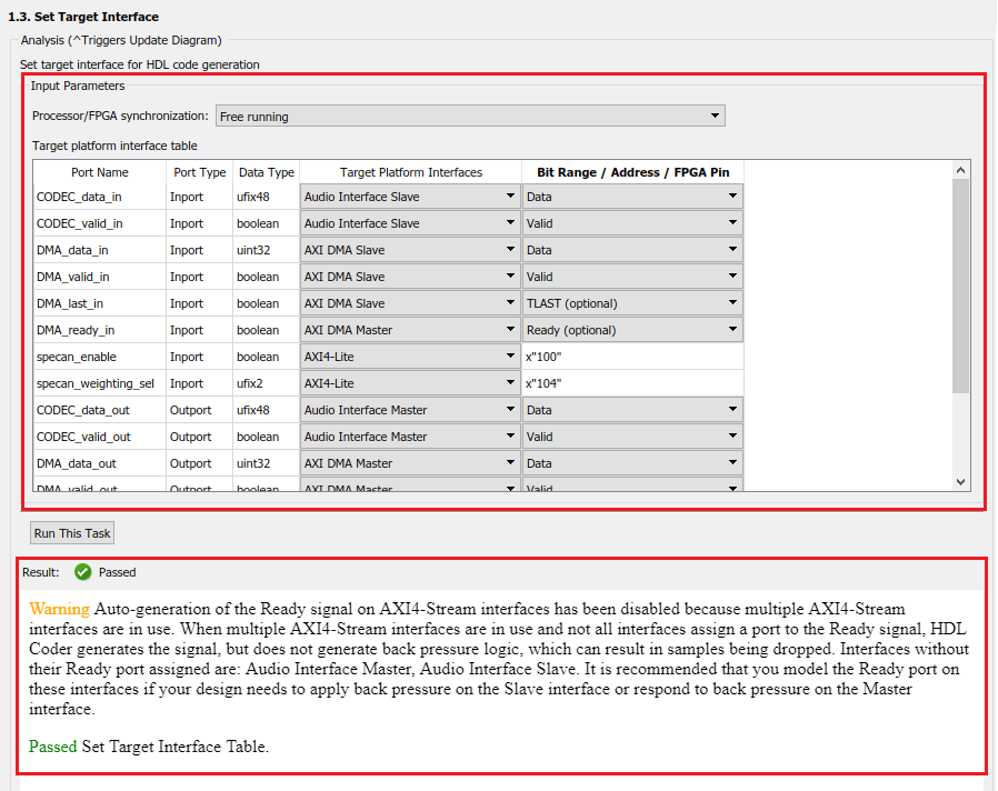
Running this task issues a warning that auto-generation of the Ready signal is disabled, and that the Audio Interface does not assign a Ready port. You can ignore the warning for this design, because back pressure has already been accounted for. Namely, the design addressed back pressure on the DMA interface by using a FIFO. On the audio codec interface, back pressure cannot be applied, so no Ready signal logic is needed.
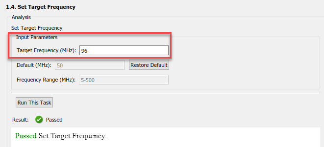
7. In the Set Target Frequency task, set the Target Frequency (MHz) to 96. Run this task.
This target frequency value makes the Oversampling factor an even integer relative to the audio sample rate of 48kHz.
8. Right-click the Generate RTL Code and IP Core task and select Run to Selected Task.
You can find the register address mapping and other documentation for the IP core in the generated IP Core Report.
Integrate IP into AXI4-Stream Audio-Compatible Reference Design
Next, in the HDL Workflow Advisor, you run the Embedded System Integration tasks to deploy the generated HDL IP core on Zynq hardware.
1. Run the Create Project task.
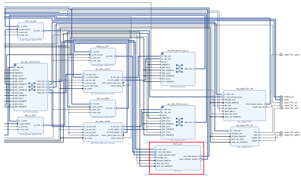
This task inserts the generated IP core into the Audio System with AXI DMA Interface reference design. As shown in the first diagram, this reference design contains the IPs to handle streaming audio data in and out of ZedBoard, and for streaming data in and out of the Processing System. The generated project is a complete ZedBoard design. It includes the algorithm part, which is the generated DUT algorithm IP, and the platform part, which is the reference design.
2. Click the link in the Result pane to open the generated Vivado project. In the Vivado tool, click Open Block Design to view the Zynq design diagram, which includes the generated HDL IP core, other audio processing IPs and the Zynq processor.
3. In the HDL Workflow Advisor, run the remaining tasks to generate the software interface model, and build and download the FPGA bitstream. Choose Download programming method in the task Program Target Device to download the FPGA bitstream onto the SD card on the Zynq board. Your design is then automatically reloaded when you power cycle the Zynq board.
Generate ARM Executable to Tune Parameters on FPGA Fabric
In task Generate Software Interface Model, a software interface model is generated.
In the generated model, AXI4-Lite driver blocks have been automatically added. However, AXI4-Stream driver blocks cannot be automatically generated, because the driver blocks expect vector inputs on the software side, but the DMA DUT ports are scalar ports. For details on how to update the software interface model with the correct driver blocks, refer to Generate IP Core with an AXI4-Stream Interface.
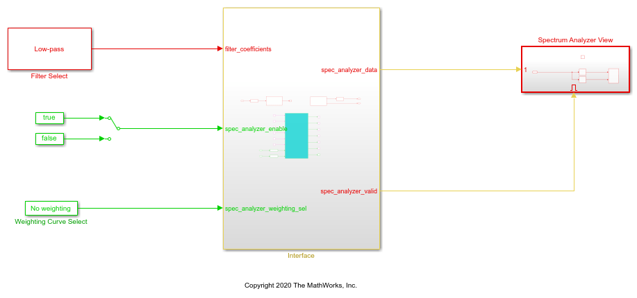
For this example, you use an updated software interface model. To open this model, run:
open_system('hdlcoder_audio_filter_multistream_sw');
To tune the parameters:
1. Click the Monitor & Tune button on the Hardware tab of model toolstrip. Embedded Coder builds the model, downloads the ARM® executable to the ZedBoard hardware, executes it, and connects the model to the running executable. While the model is running, different parameters can be tuned.
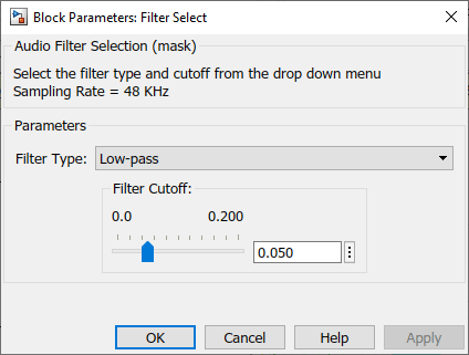
2. You can select the type of filter by using the Filter Type block parameter of the Filter Select block. The filter coefficients are calculated in this block using the fir1 function from Signal Processing Toolbox™. The coefficients are sent from the Processing System to the FPGA by using the AXI4-Stream IIO Write block, which communicates through the MM2S DMA IP.
3. The weighting curve used by the spectrum analyzer can be selected using the Curve block parameter of the Weighting Curve Select block. The selection is sent from the Processing System to the FPGA using the AXI4-Lite interface.
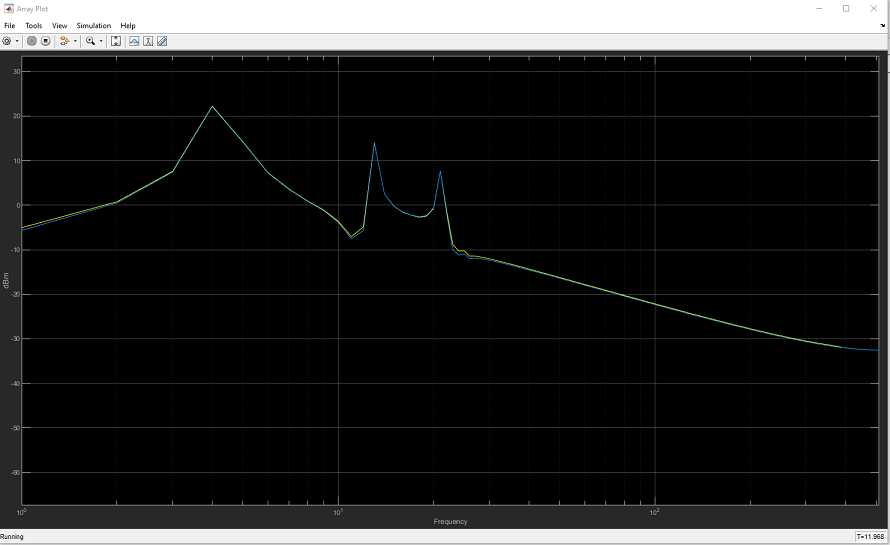
4. The spectrum analyzer output can be viewed in the Array Plot. Select a different filter type or modify the weighting curve and observe how the spectrum data changes.
The filtered audio output can be heard by plugging earphones or speakers to HPH OUT jack on the ZedBoard.