Integrate HDL IP Core with Versal AI Engine
This example shows how to model, partition, and deploy a design that leverages the processor, FPGA, and AI Engines on a Versal device.
Requirements
MATLAB® R2024b (R2024b Update only)
AMD Vitis™ Model Composer® 2023.1
AMD Vivado™ Design Suite® 2023.1
AMD Versal™ AI Core Series VCK190 Evaluation Kit
Additionally, generating AI Engine code in this example requires a Linux operating system. For Linux distributions supported by Vitis Model Composer, see Vitis Model Composer 2023.1 documentation on the AMD® website.
Introduction
The AMD Versal Adaptive SoC devices include AI Engines, which are a 2-D array of vector processors that are optimized for machine learning and advanced signal processing applications. For heterogeneous designs, the AI Engines can connect to both the processing system and programmable logic.
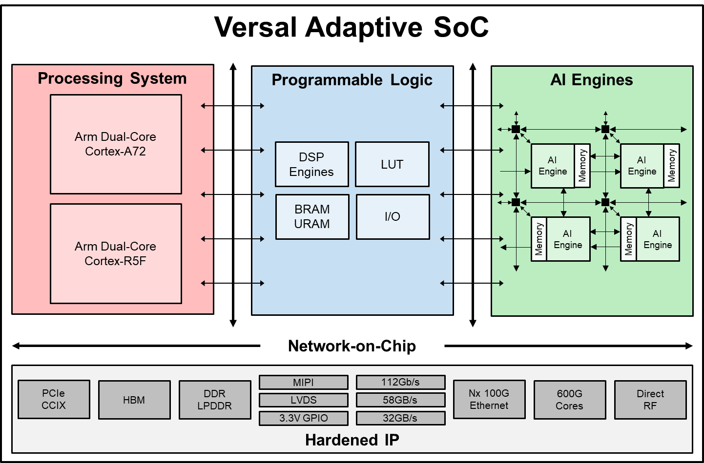
When you generate IP cores, you can use the AI Engines as part of the IP core generation workflow. You can partition your system across the processing system, programmable logic, and AI Engines allowing you to utilize all parts of your hardware and meet increasing computational demand of complex designs.
You can model and simulate a heterogeneous system in Simulink. When you use code generation to deploy the complete system to hardware:
HDL Coder generates optimized HDL code for the programmable logic, such as the FPGA.
AMD Vitis Model Composer generates code for the AI Engines.
Embedded Coder generates optimized C/C++ code for the processing system.
Finally, HDL Coder assembles all parts of the design and deploys the complete system to hardware.
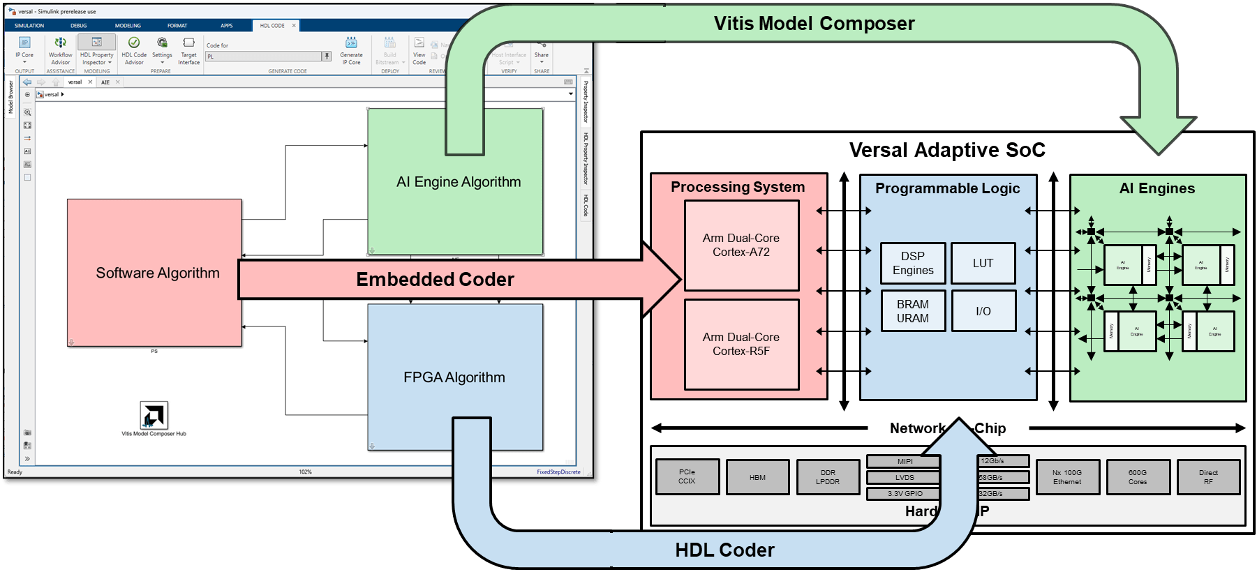
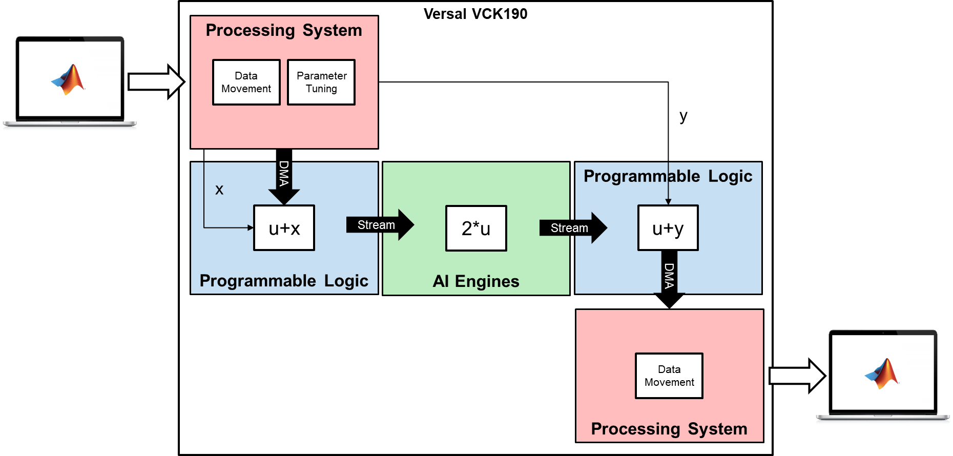
In this example, you deploy a heterogeneous system that connects the different computing domains of a Versal SoC device. You create a design where the programmable logic and AI Engines perform basic math operations, and the processing system is used for data movement and parameter tuning. Use the MATLAB host computer to prototype the design on the hardware.
The data moves between MATLAB and the hardware through the different parts of the system:
MATLAB establishes a connection to the hardware and sends a frame of data to process.
The frame transfers through the processor to the programmable logic using a direct memory access (DMA) operation.
The HDL algorithm adds an offset, then streams the data to the AI Engines.
The AI Engine algorithm doubles the input data, then streams the data back to the programmable logic.
The HDL algorithm adds another offset to the result from the AI Engines, then sends the data to the processor.
The processor sends the data back to MATLAB, where the result can be inspected further.
Optionally, MATLAB changes the offsets in the HDL algorithm through the processor.
This diagram illustrates the high-level architecture and data movement through the different parts of the system:
Examine Simulink Model and Partition Design
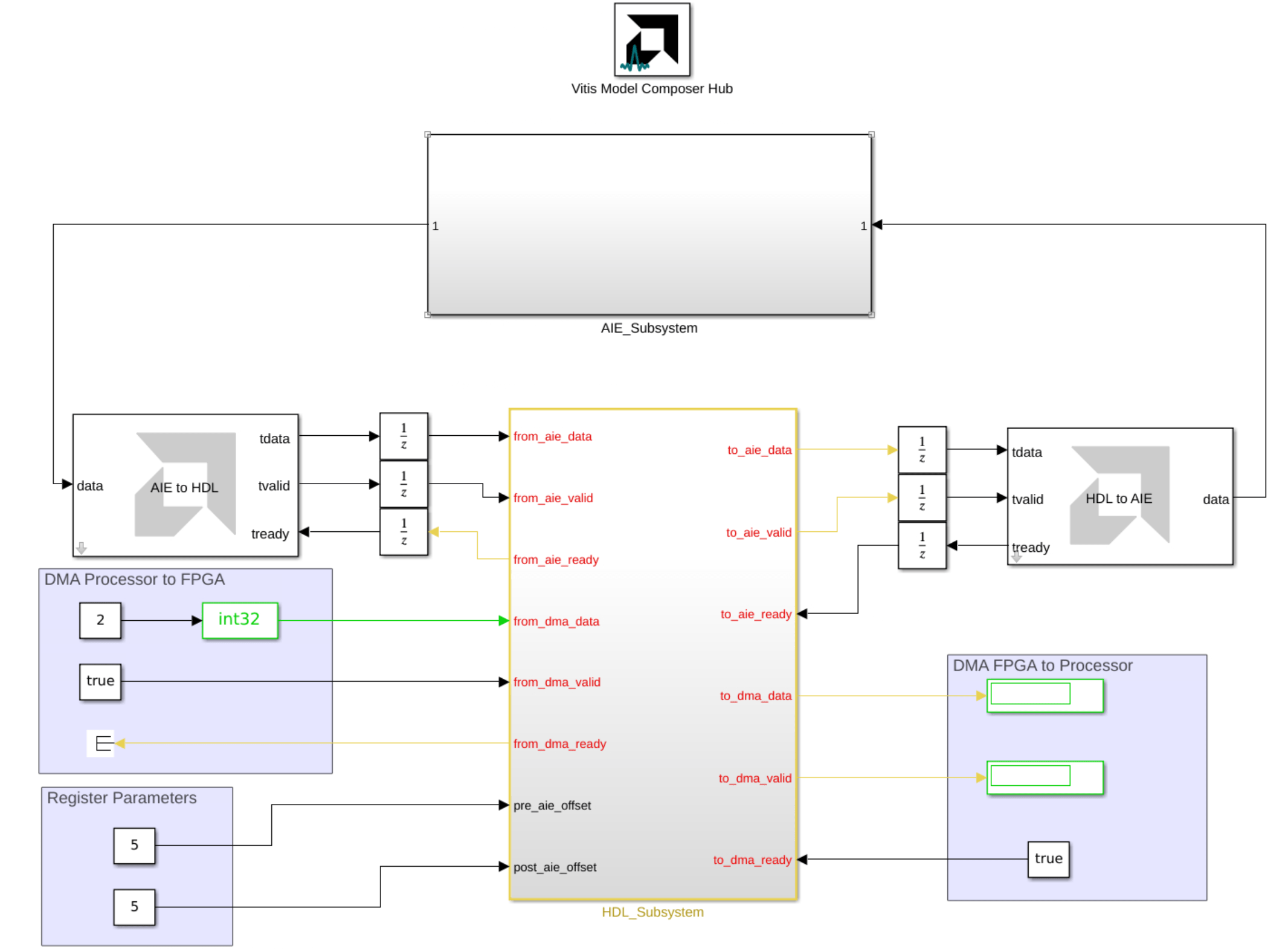
Open the Simulink model hdlcoder_aie_demo.slx, which contains an HDL algorithm subsystem and the AIE_Subsystem subsystem, which models the AI Engine algorithm.
Examine the HDL Algorithm
The HDL_Subsystem subsystem contains the algorithm for the FPGA portion of the device. The algorithm uses native Simulink blocks, and it adds an offset to the data before and after the AI Engine algorithm. In the generated code, this offset connects to a register, and you can tune the register values from the software in order to change the offset values.

Examine the AI Engine Algorithm
The AIE_Subsystem subsystem contains the algorithm for the AI Engine portion of the device. The algorithm uses an AIE Kernel block from the AMD Toolbox > AI Engine > User-Defined Functions library.

The AIE Kernel block specifies a custom kernel function for simulation and code generation. This function uses the basic kernel timestwo.cpp, which multiplies the input window by a factor of 2.
open timestwo.cpp
Generate Code for HDL and AI Engine Algorithms
Next, use the HDL Coder IP core generation workflow to generate code and build a complete system for hardware. HDL Coder generates both HDL code from the Simulink blocks and AXI interface logic that connects the IP core to the processor and AI Engines. HDL Coder invokes Vitis Model Composer to generate C++ code for the AI Engine application, then integrates the generated IP core and AI Engine application into the reference design.
Prepare Model for IP Core Generation
1. In the Apps tab, click HDL Coder. In the HDL Code tab, in the Output section, set the drop-down button to IP Core.
2. Select the HDL_Subsystem subsystem, which is the device under test (DUT) for HDL code generation. Pin the selection in the Code for box on the toolstrip.

3. Open the HDL Code Generation > Target pane of Configuration Parameters dialog by clicking the Settings button.
4. Set the Target Platform parameter to Xilinx Versal AI Core Series VCK190 Evaluation Kit. If this option does not appear, select Get more to open the Support Package Installer. In the Support Package Installer, select Xilinx FPGA and SoC Devices and follow the instructions to complete the installation. Ensure the Synthesis Tool is set to Xilinx Vivado.
5. Set the Reference Design to Default system with AXI4-Stream Interface and AI Engine.
6. Click OK.
Configure HDL IP Core Interface
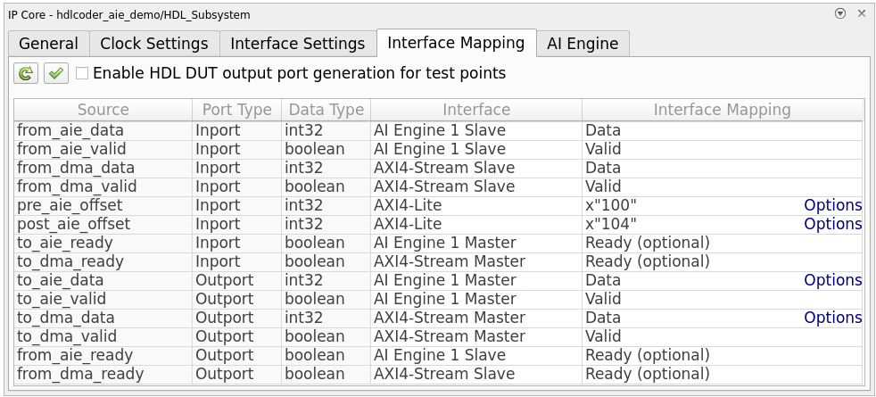
Configure the design for HDL code generation by mapping the DUT ports on the HDL subsystem to interfaces in the IP Core Editor. In this design, the HDL IP Core maps to these interfaces:
AXI4-Stream Slave: Streaming interface from the processor to IP core via DMA
AXI4-Stream Master: Streaming interface from the IP core to processor via DMA
AI Engine 1 Slave: Streaming interface from the AI Engine to IP core
AI Engine 1 Master: Streaming interface from the IP core to AI Engine
AXI4-Lite: Register interface for tuning parameters
To map the DUT ports to the corresponding interfaces:
In Simulink, in the HDL Code tab, click Target Interface to open the IP Core Editor.
Select the Interface Mapping tab. If no mapping table appears, click the Reload IP core settings
 button to compile the model and repopulate the DUT ports and their data types.
Assign DUT ports to their interfaces as shown in this table.
Configure AI Engine Interface
Configure the design for AI Engine code generation from the AI Engine tab in the IP Core Editor:
Select Enable AI Engine code generation. After you select the check box, the AI Engine settings populate on the tab.
The AI Engine subsystem and code generation folder are determined from the Vitis Model Composer Hub block in the model.
The table shows the ports of the AI Engine subsystem. For this design, the Interface Connection setting for all ports is
Auto, which means their interface connection is automatically determined based on connections in the model.

You can open the Vitis Model Composer Hub block to change the AI Engine code generation folder. The left pane of the block dialog indicates the AI Engine subsystem by using a green check mark.

Run Code Generation and Build
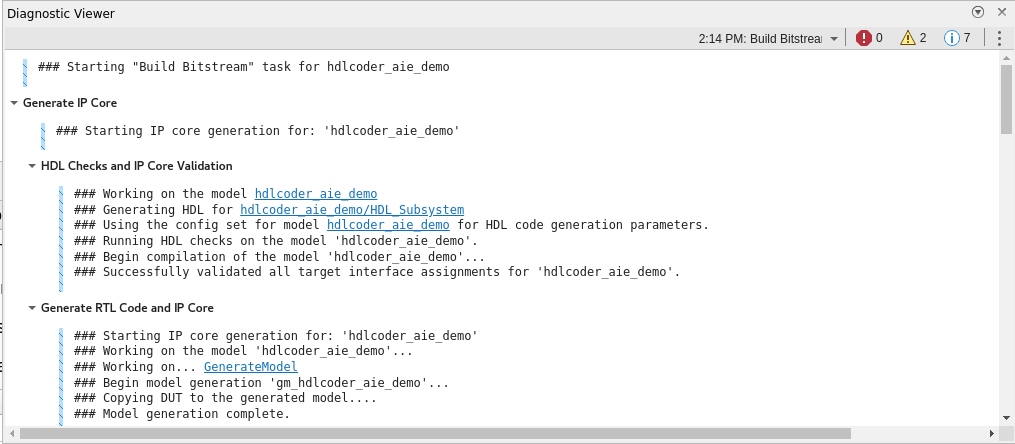
To build the complete system, and generate the HDL IP core and AI Engine code, click Build Bitstream on the HDL Code tab of the Simulink Toolstrip. This action generates the HDL IP core and AI Engine code. The Diagnostic Viewer window displays the code generation progress. After code generation completes, the build process opens an external window, runs synthesis, and creates the programming files. Monitor the external window to determine when the build process completes.
Run Design on Hardware
Next, you can prototype and verify the generated design on the hardware by creating and running a host interface script. The script contains MATLAB commands that connect to the hardware and interact with the design as it runs.
Generate Host Interface Script
To generate a host interface script, click Host Interface Script on the HDL Code tab of the Simulink Toolstrip.
This action generates two MATLAB files in your current folder:
gs_hdlcoder_aie_demo_interface.mgs_hdlcoder_aie_demo_setup.m
The script file gs_hdlcoder_aie_demo_interface.m creates an fpga hardware object that interfaces with your FPGA from MATLAB. This script contains MATLAB commands that connect to your hardware and program the FPGA, and example command that exchange data with your algorithm as it runs on hardware. The reusable setup function gs_hdlcoder_aie_demo_setup.m configures the fpga object with the hardware interfaces and ports from your DUT algorithm. This function contains DUT port objects that have the port name, direction, data type, and interface mapping information. The function maps these DUT ports to the corresponding interfaces.
Run Host Interface Script
The host interface script contains example commands to interact with the hardware. You can modify the generated script to exercise the algorithm running on hardware with your own input data.
Open the hdlcoder_aie_demo_script.mlx script which demonstrates how to modify the host interface script.
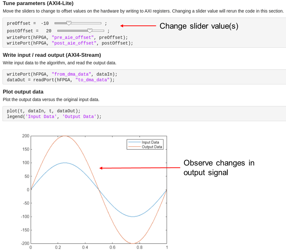
open hdlcoder_aie_demo_script.mlxThis script deploys the design on the hardware, then provides interactive controls and commands that you can use to tune the parameters, write input data to the hardware, and plot the output results from the algorithm.
Change the slider values and observe how the output data changes in the graph. The code that executes appears beneath the sliders. Each execution of the code:
Writes a new offset value to a register in the IP core
Writes one frame of input data to the hardware
Reads one frame of output data from the hardware
Plots the input and output signals on the same graph to show the result of the algorithm
When finished, clean up the connection by running the last line of the script, release(hFPGA) function to release any hardware resources used by the fpga object.
