Compare Folded and Unfolded CORDIC Architectures by Using the MATLAB Function Block
R2026bThis example generates HDL code for a folded and an equivalent unfolded fixed-point CORDIC algorithm by using the MATLAB Function block, and compares resource use to quantify the area savings.
The CORDIC algorithm computes sine and cosine through a sequence of shift-and-add micro-rotations. Use a folded CORDIC architecture when an ASIC or FPGA design is area-constrained and can tolerate multi-cycle latency for each result. Use an unfolded CORDIC architecture to maximize throughput at the cost of additional area.
The MATLAB Function block enables both architectures. The Trigonometric Function block generates only unfolded CORDIC designs.
Open the Models
Open the unfolded and folded CORDIC models. Both models use MATLAB Function blocks to compute fixed-point sine and cosine but implement different hardware architectures.
Two hardware architectures implement the CORDIC algorithm:
Unfolded: Each micro-rotation has dedicated hardware. Area scales linearly with the number of micro-rotations N, and throughput is one result per clock cycle.
Folded: A single micro-rotation unit is reused across all micro-rotations via feedback registers. Area is constant regardless of micro-rotation count, and throughput is one result every N clock cycles.
Open the hdlcordic_unfolded model. This model implements the CORDIC algorithm by using an unfolded architecture, where each of the eight micro-rotations has dedicated computation hardware.
unfolded_cordic = "hdlcordic_unfolded";
open_system(unfolded_cordic);
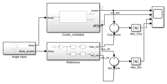
The unfolded design instantiates separate adders and shifters for each micro-rotation in a combinational chain. This produces one result per clock cycle but consumes area proportional to the number of micro-rotations.
Open the hdlcordic_eml model. This model implements the CORDIC algorithm by using a folded architecture.
folded_cordic = "hdlcordic_eml";
open_system(folded_cordic);
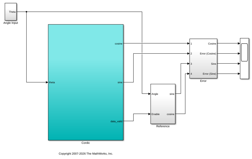
open_system(folded_cordic + "/Cordic");
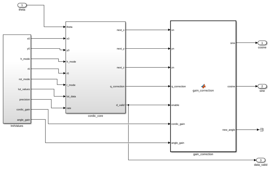
The hdlcordic_eml/Cordic/cordic_core/cordic_rotator subsystem uses three Unit Delay blocks to feed intermediate results into the computation logic for the next micro-rotation. A controller generates the micro-rotation address and selects the corresponding angle from a lookup table. After all eight micro-rotations complete, a gain correction stage applies a scaling factor. This design reuses one set of hardware across all micro-rotations, producing one result every N clock cycles.
Generate HDL Code
Generate HDL code for both models. Open the resource utilization reports to compare the hardware cost of each architecture.
hdlset_param(folded_cordic, HDLSubsystem=folded_cordic + "/Cordic");
hdlset_param(folded_cordic, TargetDirectory=fullfile(pwd, "hdlsrc"));
hdlset_param(folded_cordic, ResourceReport="on");
evalc('makehdl(folded_cordic + "/Cordic")');
web(fullfile(pwd, "hdlsrc", folded_cordic, "html", "index.html"));
hdlset_param(unfolded_cordic, HDLSubsystem=unfolded_cordic + "/Cordic_Unfolded");
hdlset_param(unfolded_cordic, TargetDirectory=fullfile(pwd, "hdlsrc_unfolded"));
hdlset_param(unfolded_cordic, ResourceReport="on");
evalc('makehdl(unfolded_cordic + "/Cordic_Unfolded")');
web(fullfile(pwd, "hdlsrc_unfolded", unfolded_cordic, "html", "index.html"));
Compare Resource Use
Display the two resource profiles side-by-side to compare the area impact of each architecture.
comparisonTable = table( ...
    [14; 46], ...
    [4; 26], ...
    [136; 0], ...
    [29; 28], ...
    [4; 0], ...
    VariableNames=["Adders", "Shifters", "RegisterBits", "Muxes", "Multipliers"], ...
    RowNames=["Folded", "Unfolded"]);
disp(comparisonTable);
                Adders    Shifters    RegisterBits    Muxes    Multipliers
                ______    ________    ____________    _____    ___________

    Folded        14          4           136          29           4
    Unfolded      46         26             0          28           0
The two architectures differ in these ways:
Adders: The unfolded design uses approximately three times the adders because it instantiates separate computation logic for each micro-rotation. The folded design reuses one set of adders across all micro-rotations.
Shift operators: The unfolded design requires a dedicated static shifter per micro-rotation, while the folded design uses only four shifters.
Registers: The unfolded design is combinational and uses no registers. The folded design uses registers to hold the intermediate results between micro-rotations.
Multiplexers: Both designs use a similar number of multiplexers. The folded design routes data between the shared rotator and the feedback path. The unfolded design uses multiplexers for quadrant correction and sign selection.
Multipliers: The folded design uses four multipliers for the gain correction scaling factor, while the unfolded design uses none because the CORDIC algorithm absorbs the gain pre-compensation into the initial value.
The folded architecture trades registers, multipliers, and throughput for significant savings in adders and shifters. The unfolded architecture produces one sine or cosine result per clock cycle, while the folded architecture produces one result every N clock cycles.
See Also
For Iterator Subsystem | makehdl | Generate resource utilization report

