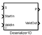
Deserializer1D
Convert scalar stream or smaller vectors to vector signal
Libraries:
HDL Coder /
HDL Operations
Description
The Deserializer1D block buffers a faster, scalar stream or vector signals into a larger, slower vector signal. The faster input signal is converted to a slower signal based on the Ratio and Idle Cycle values, the conversion changes sample time. Also, the output signal is delayed one slow signal cycle because the serialized data needs to be collected before it can be output as a vector. See the examples below for more details.
You can configure the deserialization to depend on a valid input signal ValidIn and a start signal StartIn. If the ValidIn and StartIn block parameters are both selected, data collection starts only if both ValidIn and StartIn signals are true. Consider this example:
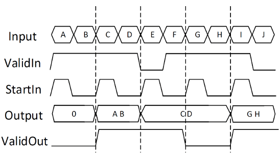
Ratio is
2and Idle Cycles is0, so each output cycle is two input signals long with all data points considered.ValidIn and StartIn are selected, so data collection can begin only when both StartIn and ValidIn signals are true.
ValidOut is selected.
In the first cycle, ValidIn and StartIn are true, so data collection begins for A and B. The block outputs the deserialized vector in the next valid cycle, so the AB vector is output in the next cycle. This is also true in the second cycle for C and D.
In the third cycle, starting at E, StartIn is true, but ValidIn is not. E is dropped. At F, ValidIn is true, but StartIn is not, so F is also dropped. Since it cannot collect data for E or F, Deserializer1D outputs the previous cycle vector, CD, but ValidOut changes to false.
Another scenario to consider is when the StartIn signal arrives too early. If the length between two StartIn signals is not long enough to collect a full ratio cycle, the insufficient signal data is dropped. Consider this example:
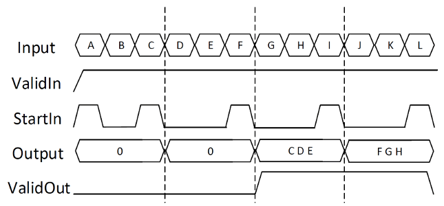
Ratio is
3, so each cycle is two sections long.Idle Cycles is
0, so all data inputs are considered.ValidIn and StartIn are selected, so data collection can begin only when both StartIn and ValidIn signals are true.
ValidOut is selected.
In the first cycle, ValidIn and StartIn are true, so data collection can begin for A and B. However, at C another StartIn signal arrives before three signals can be collected. Because the StartIn arrived early, A and B are dropped and no valid vector is collected during the first cycle. Therefore, the output of the second cycle is still zero. Deserialization begins at the StartIn at C, for C, D, and E. This vector is output at the next valid cycle, which is cycle 3. Similarly, deserialization starts again at the StartIn at F, and outputs the FGH vector in the fourth cycle.
You specify the block output for the first sampling period with the value of the Initial condition parameter.