Generate Modular Function Code for Nonvirtual Subsystems
About Nonvirtual Subsystem Code Generation
By default, when producing code for a nonvirtual subsystem, the code generator places internal data associated with a nonvirtual subsystem in the same data structure as internal data for the parent model. This can make it difficult to trace and test code, particularly for nonreusable subsystems. Also, in large models containing nonvirtual subsystems, data structures can become large and potentially difficult to compile.
To generate modular function code for nonvirtual subsystems, including atomic subsystems and conditionally executed subsystems, use the subsystem block parameter Function with separate data. This block parameter instructs the code generator to produce a block I/O and DWork data structure for the nonvirtual subsystem function that is independent from the parent model data structures. As a result, generated code for the subsystem:
Is easier to trace.
Is easier to test.
Reduces the size of a model's global data structures.
To use the Function with separate data parameter,
Configure the model with an ERT-based system target file.
Configure the subsystem to be atomic or conditionally executed.
Set the subsystem block parameter Function packaging to
Nonreusable function.
To configure your subsystem for generating modular function code, invoke the Subsystem Parameters dialog box and make a series of selections to display and enable the Function with separate data option. See Configure Subsystem for Generating Modular Function Code and Modular Function Code for Nonvirtual Subsystems for details. For limitations that apply, see Nonvirtual Subsystem Modular Function Code Limitations.
For more information about generating code for atomic subsystems, see Generate Subsystem Code as Separate Function and Files.
Configure Subsystem for Generating Modular Function Code
Verify that the model containing the subsystem uses an ERT-based system target file.
Select the subsystem for which you want to generate modular function code and open the Subsystem Parameters dialog box. The dialog box for an atomic subsystem is shown below. (In the dialog box for a conditionally executed subsystem, the dialog box option Treat as atomic unit is greyed out, and you can skip Step 3.)

If the block parameter Treat as atomic unit is available for selection but not selected, the subsystem is neither atomic nor conditionally executed. Select the parameter Treat as atomic unit, which enables the Function packaging parameter on the Code Generation tab. Select the Code Generation tab.

For the Function packaging parameter, select
Nonreusable function. After you make this selection, the Function with separate data parameter is displayed.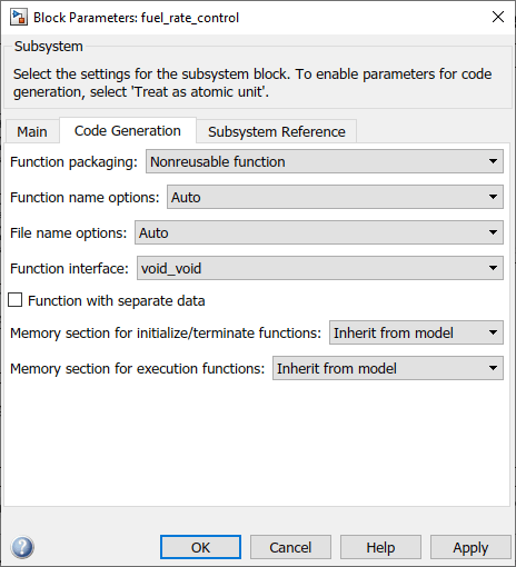
Before you generate code for the nonvirtual subsystem with the Function with separate dataparameter selected, consider generating function code with the parameter cleared and save the generated function
.cand.hfiles in a separate directory for later comparison.Select the Function with separate data parameter. Additional parameters appear.

To control the naming of the generated subsystem function and the subsystem files, modify subsystem parameters Function name options and File name options.
Save your subsystem parameter changes and exit the dialog box by clicking OK.
Generate code for the subsystem and examine the generated files, including the function
.cand.hfiles named according to your subsystem parameter specifications.
For more information on generating code for nonvirtual subsystems, see Generate Subsystem Code as Separate Function and Files. For examples of generated subsystem function code, see Modular Function Code for Nonvirtual Subsystems.
Modular Function Code for Nonvirtual Subsystems
This example shows how to generate nonvirtual subsystem function code with the Function with separate data parameter cleared and selected and compares the results.
Open example model
SubsystemAtomic.openExample("SubsystemAtomic")Open the Embedded Coder app. Change the system target file to
ert.tlc.
This model shows how to preserve the boundary of a virtual subsystem. When you select subsystem block parameter Treat as atomic unit, the code that the code generator produces for the subsystem executes as an atomic unit. When configured as atomic, you can specify how the code generator represents the subsystem by setting the Function Packaging parameter on the Code Generation tab. You can specify that the subsystem is translated to one of these types of implementation:
Inline: Inlined subsystem code at call sites.Function:void/voidfunction with I/O and internal data in the model global data structure.Reusable Function: Reentrant function with data passed in as function arguments.Auto: Code generator optimizes the implementation based on context.
Double-click the
SS1subsystem and examine the contents.
Then, close the subsystem window.
Right-click the
SS1subsystem, and then click the Block Parameters button . Examine the settings. Simulink® and the code generator can avoid artificial algebraic loops when you make
the subsystem atomic and enable the subsystem parameter Minimize artificial
algebraic loop occurrences.
. Examine the settings. Simulink® and the code generator can avoid artificial algebraic loops when you make
the subsystem atomic and enable the subsystem parameter Minimize artificial
algebraic loop occurrences.Create a variant of
SubsystemAtomicthat shows function code without data separation.In the Subsystem Parameters dialog box,
In the Main tab, select Treat as atomic unit.
In the Code Generation tab:
Set Function packaging to
Nonreusable function.Set Function name options to
User specified.Set Function name to
myfun.Set File name options to
Use
                              function name
. This setting is optional but simplifies the later task of code comparison by causing the atomic subsystem function code to be generated into filesmyfun.candmyfun.h.
Do not select the Function with separate data parameter.
Click Apply to apply the changes and click OK to exit the dialog box.
Save the model variant with a unique file name (for example,
SubsystemAtomic1) to a writable location.
Create a variant of
SubsystemAtomicthat shows function code with data separation.Open model
SubsystemAtomic.Open the Embedded Coder app. Change the system target file to
ert.tlc.In the model canvas, right-click the SS1 subsystem and select Block Parameters (Subsystem). In the Subsystem Parameters dialog box,
In the Main tab, select Treat as atomic unit.
In the Code Generation tab:
Set Function packaging to
Nonreusable function.Set Function name options to
User specified.Set Function name to
myfun.Set File name options to
Use function name.Select Function with separate data.
Click Apply to apply the change and click OK to exit the dialog box.
Save the model variant with a unique file name (for example,
SubsystemAtomic2) to a writable location.
Generate code for each model (for example,
SubsystemAtomic1andSubsystemAtomic2).Compare the
model.c.handmyfun.c/.hfiles generated for the two models. For code comparison discussion, see H File Differences for Nonvirtual Subsystem Function Data Separation and C File Differences for Nonvirtual Subsystem Function Data Separation.In this example, there are not significant differences in the generated variants of
ert_main.c,model_private.hmodel_types.hrtwtypes.h.
H File Differences for Nonvirtual Subsystem Function Data Separation
Selecting Function with separate data causes the code generator to place type definitions for subsystem data in the
myfun.hfile forSubsystemAtomic2:/* Block states (default storage) for system '<Root>/SS1' */ typedef struct { real_T Integrator_DSTATE; /* '<S1>/Integrator' */ } DW_myfun_T;For
SubsystemAtomic1, type definitions for subsystem data belong to the model and appear inSubsystemAtomic1.h:/* Block signals (default storage) */ typedef struct { real_T Sum; /* '<Root>/Sum' */ } B_SubsystemAtomic_1_T; /* Block states (default storage) for system '<Root>' */ typedef struct { real_T Integrator_DSTATE; /* '<S1>/Integrator' */ } DW_SubsystemAtomic_1_T;Selecting Function with separate data generates the following external declarations in the
myfun.hfile forSubsystemAtomic2:/* Extern declarations of internal data for system '<Root>/SS1' */ extern DW_myfun_T myfun_DW; extern void myfun_Update(void); extern void myfun(void);
By contrast, the generated code for
SubsystemAtomic1contains model-level external declarations for the subsystemBlockIOandD_Workdata, inSubsystemAtomic1.h:/* Block signals (default storage) */ extern B_SubsystemAtomic_1_T SubsystemAtomic_1_B; /* Block states (default storage) */ extern DW_SubsystemAtomic_1_T SubsystemAtomic_1_DW;
C File Differences for Nonvirtual Subsystem Function Data Separation
Selecting Function with separate data causes a separate subsystem initialize function,
myfun_initialize, to be generated in themyfun.cfile forSubsystemAtomic2:void myfun_initialize(void) { { ((real_T*)&SubsystemAtomic2_myfunB.Integrator)[0] = 0.0; } SubsystemAtomic2_myfunDW.Integrator_DSTATE = 0.0; }The subsystem initialize function in
myfun.cis invoked by the model initialize function inSubsystemAtomic2.c:/* Model initialize function */ void SubsystemAtomic2_initialize(void) { ... /* Initialize subsystem data */ myfun_initialize(); }By contrast, for
SubsystemAtomic1, subsystem data is initialized by the model initialize function inSubsystemAtomic1.c:/* Model initialize function */ void SubsystemAtomic1_initialize(void) { ... /* block I/O */ { ... ((real_T*)&SubsystemAtomic1_B.Integrator)[0] = 0.0; } /* states (dwork) */ SubsystemAtomic1_DWork.Integrator_DSTATE = 0.0; ... }Selecting Function with separate data generates the following declarations in the
myfun.cfile forSubsystemAtomic2:/* Declare variables for internal data of system '<Root>/SS1' */ DW_myfun_T myfun_DW;
By contrast, the generated code for
SubsystemAtomic1contains model-level declarations for the subsystemsBlockIOandD_Workdata, inSubsystemAtomic1.c:/* Block signals (default storage) */ B_SubsystemAtomic_1_T SubsystemAtomic_1_B; /* Block states (default storage) */ DW_SubsystemAtomic_1_T SubsystemAtomic_1_DW;
Selecting Function with separate data generates identifier naming that reflects the subsystem orientation of data items. The references to subsystem data in subsystem functions, such as
myfunandmyfun_update, are in the modelmodel_stepmyfunforSubsystemAtomic2/* DiscreteIntegrator: '<S1>/Integrator' */ SubsystemAtomic_2_Y.Out1 = myfun_DW.Integrator_DSTATE;
to the corresponding code from
myfunforSubsystemAtomic1./* DiscreteIntegrator: '<S1>/Integrator' */ SubsystemAtomic_1_Y.Out1 = SubsystemAtomic_1_DW.Integrator_DSTATE;
Nonvirtual Subsystem Modular Function Code Limitations
Nonvirtual subsystem block parameter Function with separate data has the following limitations:
The parameter is available for models configured with an ERT-based system target file.
The nonvirtual subsystem to which the parameter is applied cannot have multiple sample times or continuous sample times; that is, the subsystem must be single-rate with a discrete sample time.
The nonvirtual subsystem cannot contain continuous states.
The nonvirtual subsystem cannot output function call signals.
The nonvirtual subsystem cannot contain noninlined S-functions.
The generated files for the nonvirtual subsystem will reference model-wide header files, such as
model.hmodel_private.hThe parameter is incompatible with the
Reusable functionsetting for model configuration parameter Code interface packaging. Selecting both parameters generates an error.
When you select the parameter for a subsystem, the model that contains the subsystem cannot contain a Data Store Memory block with Share across model instances selected. See Data Store Memory.