Digital Signal Processing Design for FPGAs and ASICs
Deploying algorithmic models to FPGA hardware makes it possible to do real time testing and verification. However, designing digital signal processing systems for hardware requires design tradeoffs between hardware resources and throughput. You can speed up hardware design and deployment by using HDL-optimized blocks that have hardware-suitable interfaces and architectures, application examples that implement common DSP algorithms, and automatic HDL code generation. You can also use hardware support packages to assist with deploying and verifying your design on real hardware.
MathWorks® HDL products, such as DSP HDL Toolbox™, allow you to start with a mathematical model, such as MATLAB® code from DSP System Toolbox™, and design a hardware implementation of that algorithm that is suitable for FPGAs and ASICs.
From Mathematical Algorithm to Hardware Implementation
DSP design often starts with algorithm development and testing using MATLAB functions. MATLAB code, which usually operates on matrices of floating-point data, is good for developing mathematical algorithms, manipulating large data sets, and visualizing data.
Hardware engineers typically receive a mathematical specification from an algorithm team, and reimplement the algorithm for hardware. Hardware designs require tradeoffs of resource usage for clock speed and overall throughput. Usually this tradeoff means operating on streaming data, and using some logic to control the storage and flow of data. Hardware engineers usually work in hardware description languages (HDLs), like VHDL and Verilog, that provide cycle-based modeling and parallelism.
To bridge this gap between mathematical algorithm and hardware implementation, use the MATLAB algorithm model as a starting point for hardware implementation. Make incremental changes to the design to make it suitable for hardware, and progress towards a Simulink® model that you can use to automatically generate HDL code by using HDL Coder™.
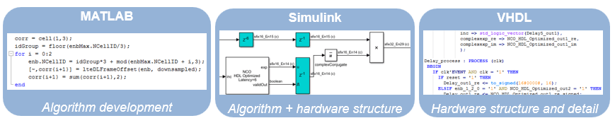
This diagram shows the design progression from mathematical algorithm in MATLAB, to hardware-compatible implementation in Simulink, and then the generated VHDL code.
While both MATLAB and Simulink support automatic generation of HDL code, you must construct your design with hardware requirements in mind, and Simulink is better-suited for cycle-based modeling for hardware. It can represent parallel data paths and streaming data with control signals to manage the timing of the data stream. To aid in fixed-point type choices, it clearly visualizes data type propagation in the design. It also allows for easy pipelining of mathematical operations to improve maximum clock frequency in hardware.
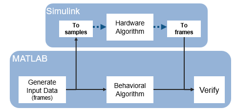
While you create your hardware-ready design, use the MATLAB algorithm as a "golden reference" to verify that each version of the design still meets the mathematical requirements. The workflow shown in the diagram uses MATLAB and Simulink as collaboration and communication tools between the algorithm and hardware design teams.
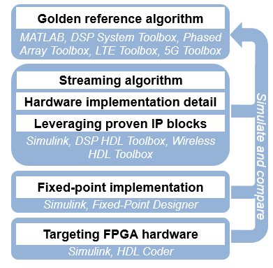
For instance, when designing digital filters, you can use DSP System Toolbox functions to create a golden reference in MATLAB. Then transition to Simulink and create a hardware-compatible implementation by using library blocks from DSP HDL Toolbox and Wireless HDL Toolbox™. You can reuse test and data generation infrastructure from MATLAB by importing data from MATLAB to your Simulink model and returning the output of the model to MATLAB to verify it against the "golden reference".
HDL-Optimized Blocks
Library blocks from DSP HDL Toolbox implement filters, FFTs, decimators, interpolators, and an NCO for use in digital signal processing systems. These blocks use a standard streaming data interface for hardware. This interface makes it easy to connect parts of the algorithm together, and includes control signals that manage the flow of data and mark frame boundaries. These blocks support automatic HDL code generation with HDL Coder. You can also use blocks from Communications Toolbox™ and DSP System Toolbox that support HDL code generation.
The blocks provide hardware-suitable architectures that optimize resource use, such as including adder and multiplier pipelining to fit well into FPGA DSP slices. They also support automatic and configurable fixed-point data types. Using predefined blocks also allows you to try different parameter configurations and architectures without changing the rest of the design.
For lists of blocks that support HDL code generation, see DSP HDL Toolbox Block List (HDL Code Generation), Wireless HDL Toolbox Block List (HDL Code Generation) (Wireless HDL Toolbox), Communications Toolbox Block List (HDL Code Generation) (Communications Toolbox), and DSP System Toolbox Block List (HDL Code Generation).
Generate HDL Code and Prototype on FPGA
DSP HDL Toolbox provides blocks that support HDL code generation. To generate HDL code from designs that use these blocks, you must have an HDL Coder license. HDL Coder produces device-independent code with signal names that correspond to the Simulink model. HDL Coder also provides a tool to drive the FPGA synthesis and targeting process, and enables you to generate scripts and test benches for use with third-party HDL simulators.
To assist with the setup and targeting of programmable logic on a prototype board, and to verify your wireless communications system design on hardware, download a hardware support package such as HDL Coder Support Package for Xilinx® RFSoC Devices.