Place Cameras on Actors in the Unreal Editor
To visualize objects in an Unreal® Editor scene, you can place cameras on static or custom actors in the scene. To start, you need the Automated Driving Toolbox Interface for Unreal Engine Projects support package. See Install Support Package for Customizing Scenes.
To follow this workflow, you should be comfortable using Unreal Engine®. Make sure that you have Visual Studio® 2022 installed on your computer.
Place Camera on Static Actor
Follow these steps to place a Simulation 3D Camera block that is offset from a cone in the Unreal Editor. Although this example uses the To Video Display block from Computer Vision Toolbox™, you can use a different visualization block to display the image.
In a Simulink® model, add the Simulation 3D Scene Configuration, Simulation 3D Camera, and To Video Display blocks.
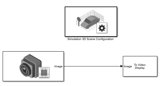
Set these block parameters. In the Simulation 3D Scene Configuration block, select Open Unreal Editor.
Block Parameter Settings Simulation 3D Scene Configuration
Scene Source —
Unreal EditorProject — Specify the path and name of the support package project file. For example,
C:\Local\AutoVrtlEnv\AutoVrtlEnv.uproject
Simulation 3D Camera
Sensor identifier —
1Parent name —
Scene
                                                  Origin
Mounting location —
OriginSpecify offset —
onRelative translation [X, Y, Z] (m) —
[-6, 0, 2]This offsets the camera location from the cone mounting location, 6 m behind, and 2 m up.
Relative rotation [Roll, Pitch, Yaw] —
[0, 15, 0]
In the Unreal Editor, from the File > Open Level, select
HwStraight. From the Place Actors tab, add a Sim 3d Scene Cap to the world, scene, or map.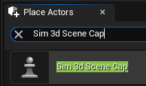
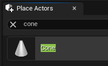
In the Unreal Editor, from the Place Actors tab, add a Cone to the world, scene, or map.
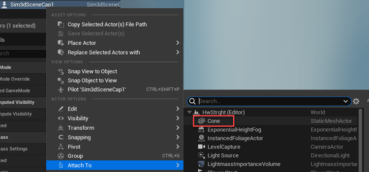
On the Outliner tab, right-click the Sim3DSceneCap and attach it to the Cone.
On the Details tab, under Transform, add a location offset of
-500,0,100in the X, Y, and Z world coordinate system, respectively. This attaches the camera 500 cm behind the cone and 100 cm above it. The values match the Simulation 3D Camera block parameter Relative translation [X, Y, Z] (m) value.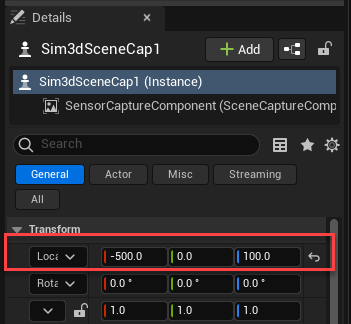
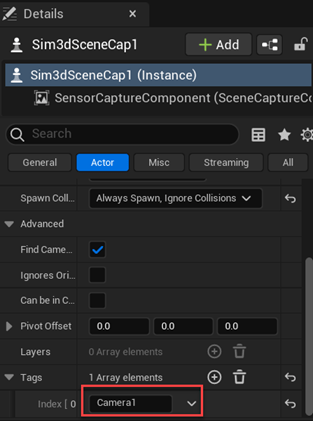
On the Details tab, tag the Sim3DSceneCap with the name IdealCamera1.
Run the simulation.
In the Simulink model, click Run.
Because the source of the scenes is the project opened in the Unreal Editor, the simulation does not start.
Verify that the Diagnostic Viewer window in Simulink displays this message:
In the Simulation 3D Scene Configuration block, you set the scene source to 'Unreal Editor'. In Unreal Editor, select 'Play' to view the scene.This message confirms that Simulink has instantiated the vehicles and other assets in the Unreal Engine 3D environment.
In the Unreal Editor, click Play. The simulation runs in the scene currently open in the Unreal Editor.
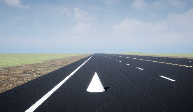
Observe the results in the To Video display window. The window displays the image from the camera.
Place Camera on Vehicle in Custom Project
Follow these steps to create a custom Unreal Engine project and place a camera on a vehicle in the project. Although the example uses the To Video Display block from Computer Vision Toolbox, you can use a different visualization block to display the image.
To start, you need the Automated Driving Toolbox Interface for Unreal Engine Projects support package. See Install Support Package for Customizing Scenes.
In a Simulink model, add the Simulation 3D Scene Configuration, Simulation 3D Camera, and To Video Display blocks.
Save the model.
Create a new project using the Vehicle template from the Epic Games Launcher by Epic Games®.
In the Epic Games Launcher, launch Unreal Engine 5.3.

For more information about the Epic Games Launcher, see Unreal Engine.
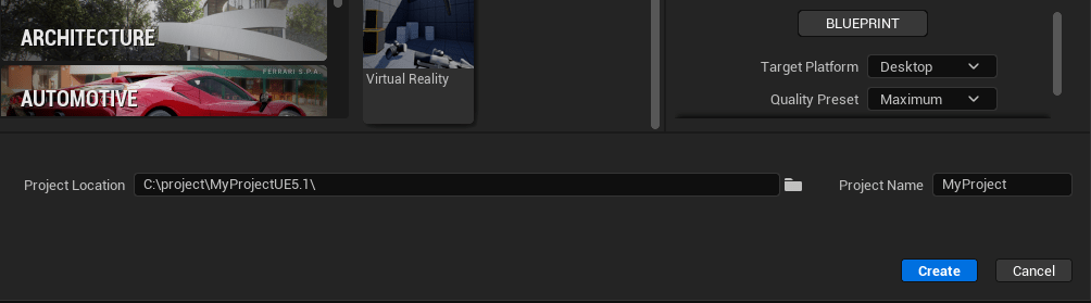
In the Unreal Project Browser, select Games and Vehicle.

In the browser, create a Blueprint or C++ project. Provide a project name and location. Click Create.
The Epic Games Launcher creates a new project and opens the Unreal Editor.
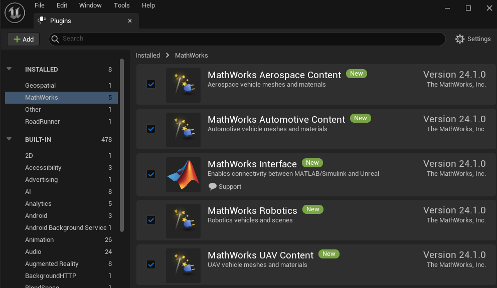
Enable the MathWorks® plugins.
Select Edit > Plugins.
On the Plugins tab, navigate to MathWorks. Select Enabled for the content you want to enable, including MathWorks Interface.
Save the project. Close the Unreal Editor.
Open the Simulink model that you saved in step 1. Set these block parameters.
Block Parameter Settings Simulation 3D Scene Configuration
Scene Source —
Unreal EditorProject — Specify the path an project that you saved in step 2. For example,
myProjectPath\myProject.uproject
Simulation 3D Camera
Sensor identifier —
1Parent name —
Scene OriginMounting location —
Origin
In the Simulation 3D Scene Configuration block, select Open Unreal Editor.
Add the vehicle
OffroadCar_Pawn. In the Unreal Editor, in the Content Browser, navigate to All > Content > VehicleTemplate > Blueprints and selectOffroadCar_Pawn. Drag and release the vehicle into the world, scene, or map. In the Details panel, set Auto Possess Player toPlayer 0.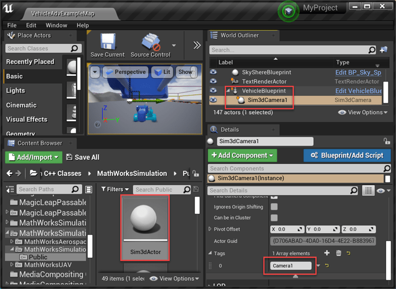
In the Unreal Editor, from the Place Actors tab, add a Sim 3d Scene Cap to the world, scene, or map.
In the Outliner tab, drag and release the camera onto the vehicle
OffroadCar_Pawnand choose a vehicle socket or bone to attach the camera to. For this example, select None.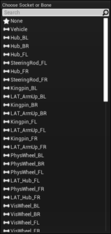
On the Details tab, tag the
Sim3dSceneCapwith the nameIdealCamera1.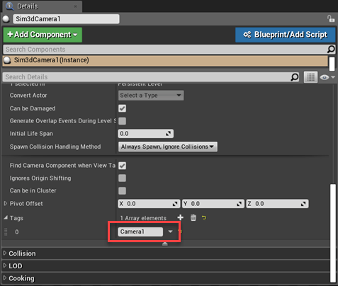
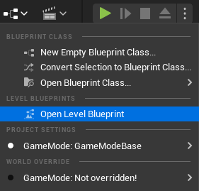
Set the parent class.
Under Blueprints, click Open Level Blueprint, and select Class Settings.
In the Class Options, set Parent Class to
Sim 3d Level Script Actor.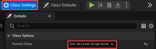
Optionally, use a level blueprint to set up a camera view that overrides the default view in the Unreal Editor. For information about creating level blueprints, see Set up Camera View (Optional) (Vehicle Dynamics Blockset).
Save the project.
Run the simulation.
In the Simulink model, click Run.
Because the source of the scenes is the project opened in the Unreal Editor, the simulation does not start.
Verify that the Diagnostic Viewer window in Simulink displays this message:
In the Simulation 3D Scene Configuration block, you set the scene source to 'Unreal Editor'. In Unreal Editor, select 'Play' to view the scene.This message confirms that Simulink has instantiated the vehicles and other assets in the Unreal Engine 3D environment.
In the Unreal Editor, click Play. The simulation runs in the scene currently open in the Unreal Editor.
See Also
Simulation 3D Scene Configuration | Simulation 3D Camera