Generate V2X MAP Message from RoadRunner
This example shows how to generate a MAP message per the China Society of Automotive Engineers (CSAE) standards [1] and model a roadside unit (RSU) to transmit MAP messages using vehicle-to-everything (V2X) communication.
Introduction
In vehicle-to-everything (V2X) communication, a connected vehicle interacts with roadside units (RSUs) to obtain vital information about road infrastructure. These RSUs transmit MAP messages, which contain detailed geographic road information. Each MAP message includes essential data about lane geometry and lane connectivity at intersections. This information aids in navigation and critical decision-making within interconnected road networks. When combined with basic safety messages (BSMs), the MAP messages significantly enhance the accuracy of localization and tracking of target vehicles at intersections, thereby contributing to improved safety on the roads.
This example explores MAP messages, RSU modeling, and shows how to generate MAP messages in compliance with CSAE standards using RoadRunner HD Map. In this example, you:
Set Up Environment — Configure MATLAB® to interact with RoadRunner Scenario.
Explore Scene and Scenario — Explore the RoadRunner scene and scenario, which defines actions for the ego vehicle and other actors.
Generate MAP Message — Generate a MAP message for a scene using the RoadRunner HD Map.
Explore Model — Explore the Simulink® model configured for cosimulation with RoadRunner. The model includes RoadRunner interfaces, an RSU for transmitting MAP messages, and a visualization system for observing the MAP messages.
Model Road Side Unit — Model an RSU that transmits local geographic information to the vehicles within its range.
Simulate and Visualize MAP Message — Simulate the test scenario, and visualize the MAP messages transmitted from the RSU.
Set Up Environment
This section shows how to set up the environment to cosimulate with RoadRunner Scenario.
Start the RoadRunner application interactively by using the roadrunnerSetup function. When the function opens a dialog box, specify the RoadRunner Project Folder and RoadRunner Installation Folder locations.
rrApp = roadrunnerSetup;
The rrApp RoadRunner object enables you to interact with RoadRunner from the MATLAB workspace. You can open the scenario and update scenario variables using this object. For more information on this object, see roadrunner.
This example uses these files, which you must add to the RoadRunner project.
GenerateMapMessage.rrscenario— Scenario file based on theUSCityBlockBidirectional.rrscenescene included with the RoadRunner Asset Library.GenerateMapMessage.rrbehavior.rrmeta— Behavior file to associate with the ego vehicle in RoadRunner Scenario, implemented using the Simulink model.
Copy these files to the RoadRunner project.
copyfile("GenerateMapMessage.rrscenario",fullfile(rrApp.status.Project.Filename,"Scenarios"))
copyfile("GenerateMapMessage.rrbehavior.rrmeta",fullfile(rrApp.status.Project.Filename,"Assets/Behaviors/"))
Explore Scene and Scenario
This example uses USCityBlockBidirectional scene. This scene is a 3D representation of a compact city block with 15 intersections. All roads in the scene are two-way roads with four lanes.
Open the scene.
openScene(rrApp,"USCityBlockBidirectional.rrscene")
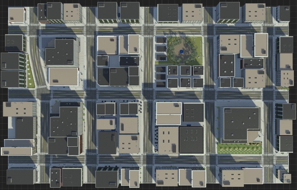
To connect to the RoadRunner Scenario server for cosimulation, first open a new empty scenario using the newScenario function, and then connect to the RoadRunner Scenario server using the createSimulation function. Once connected, enable data logging.
newScenario(rrApp);
rrSim = createSimulation(rrApp);
set(rrSim,Logging="on")
Connection status: 1
Connected to RoadRunner Scenario server on localhost:54322, with client id {dac5087f-9d90-4b4d-9e46-1afbf70d431c}
rrSim is a ScenarioSimulation object. Use this object to set variables and to read scenario-related information. Set the simulation to run at a step size of 0.1.
Ts = 0.1;
set(rrSim,StepSize=Ts)
Open the scenario.
openScenario(rrApp,"GenerateMapMessage.rrscenario")
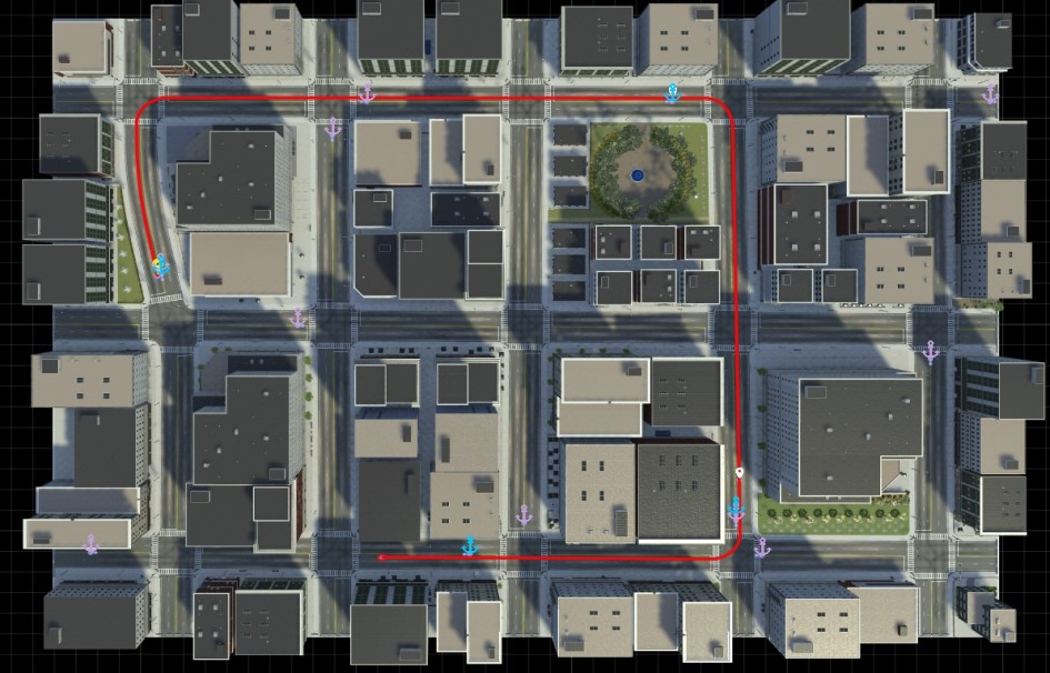
The scenario contains an ego vehicle that follows the specified path with a constant velocity.
Generate MAP Message
This example generates MAP messages as per the CSAE standard. Each message contains these elements:
Node — A node is the fundamental unit of a map. It can represent an intersection or an endpoint of a road segment. Node attributes include name, ID, location, and the set of upstream links connected to it.
Link — A link represents a connection between two nodes, starting from an upstream node and ending at a downstream node.
Lane — Each link consists of multiple lanes. Each lane contains information about lane maneuver, speed limit, lane width, and connections with other lanes.
Get the RoadRunner HD Map, which contains detailed information about lanes, lane boundaries, and intersections.
rrHDMap = get(rrSim,"Map");
Plot the RoadRunner HD Map.
plot(rrHDMap)
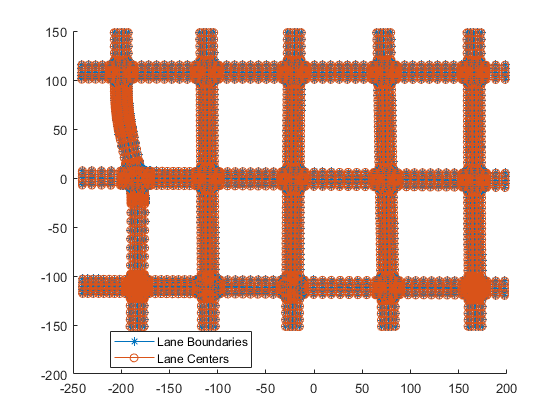
Define the geographic scene origin, specified as a three-element vector of the form [ latitude longitude altitude].
sceneOrigin = [42.3648 -71.0214 10.0];
Generate the V2X MAP message as per the CSAE standard by using the helperGenerateV2XMap function. Generating the V2X MAP message for a large scene can be time consuming. This example ships the precomputed V2X MAP message USCityBlockBidirectionalV2XMapMessage.mat corresponding to USCityBlockBidirectional scene. If the current scene is USCityBlockBidirectional the MAP message is loaded from the .mat file. For any other scenes, the V2X MAP message is generated using the helperGenerateV2XMap function.
[~,currentScene,~] = fileparts(rrApp.status.Scene.Filename);
if currentScene == "USCityBlockBidirectional"
    load('USCityBlockBidirectionalV2XMapMessage.mat')
else
    v2xMapMsg = helperGenerateV2XMap(rrHDMap,sceneOrigin);
end
Visualize the MAP message using the helperPlotV2XMap function.
helperPlotV2XMap(v2xMapMsg);
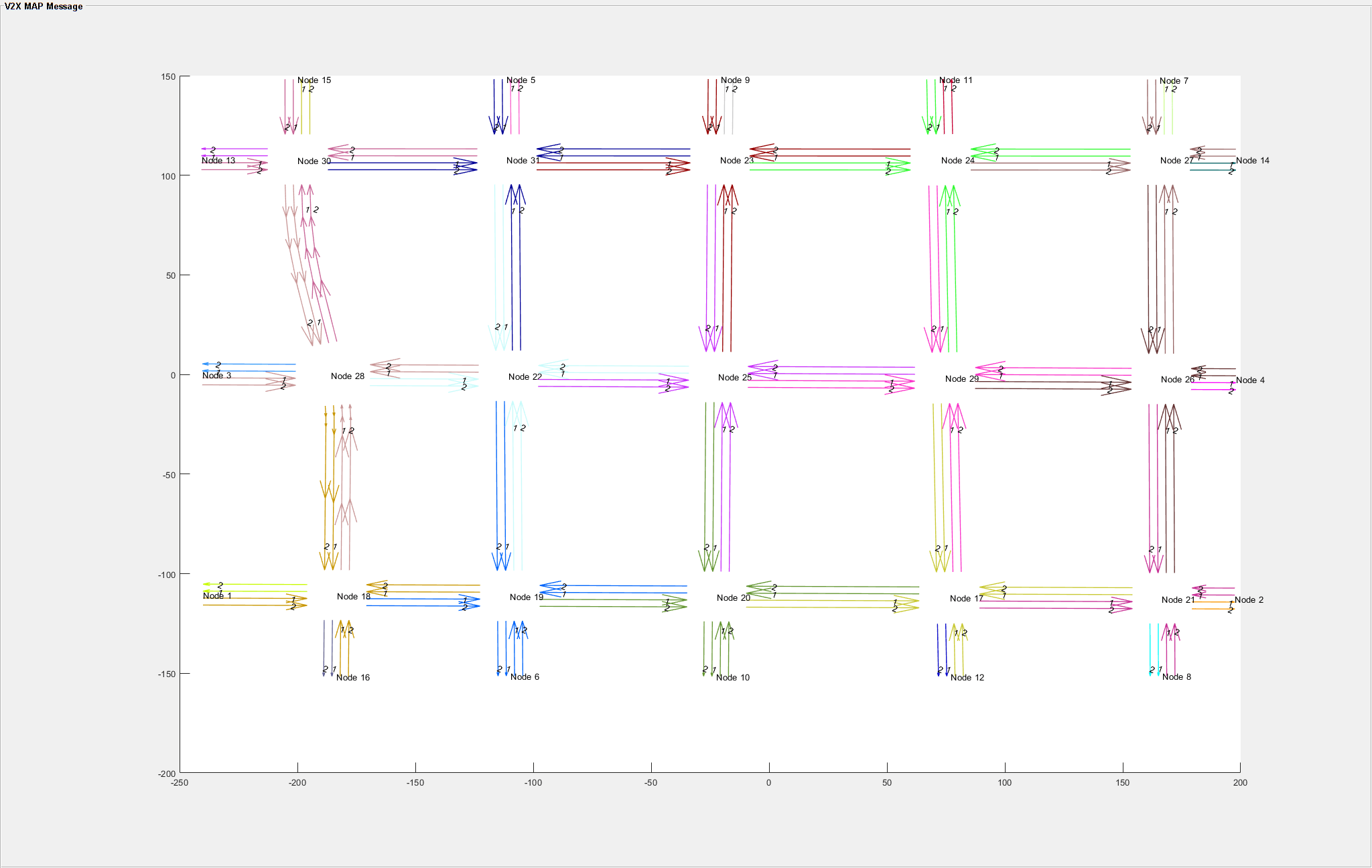
The plot shows the entire network of nodes, links, and lanes in the USCityBlockBidirectional scene's V2X MAP message. This map covers a region with a total of 31 nodes, including 15 junctions and 16 road ends. Each node is connected to its neighbors by links, and all links associated with a particular node are shown in the same color. The lanes in each link are numbered from left to right, starting with one for the leftmost lane. The number of arrows in each lane corresponds to the number of three-dimensional points defining that lane. A lane with a single arrow is defined by just two points.
Explore Model
This example demonstrates how vehicle receives MAP messages from RSU through the GenerateMapMessage model. During simulation, the model updates the ego vehicle's position along a predefined path and simulates a RSU that generates the V2X MAP message of the ego vehicle region. The RSU in the model generates the V2X MAP message corresponding to the ego vehicle region by using the MAP message of the entire scene that was generated in the previous section, and the ego vehicle runtime information.
Open the model.
open_system("GenerateMapMessage")
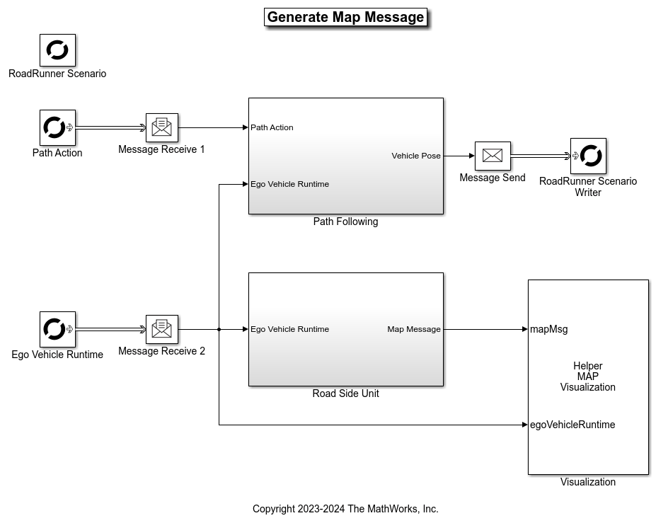
The model contains RoadRunner Scenario blocks, which configure, read from, and write to RoadRunner Scenario, as well as these modules:
Road Side Unit— System object™ that implements an RSU. Using the generated MAP message of the entire scene and the ego vehicles position the RSU transmits MAP message of the region in which the ego vehicle is present.Path Following— This subsystem enables the ego vehicle to follow the path specified in the RoadRunner scenario. It takes the ego pose and the path as input and writes back the updated ego pose to RoadRunner.Visualization— Visualizes the scenario along with the MAP message received from the RSU.
The RoadRunner Scenario blocks consist of:
RoadRunner Scenario— Defines the interface for an actor model.Path Action— RoadRunner Scenario Reader block that reads the path of the ego vehicle.Ego Vehicle Runtime— RoadRunner Scenario Reader block that reads ego vehicle runtime information.RoadRunner Scenario Writer— Writes the ego vehicle runtime information to RoadRunner Scenario.
Model Road Side Unit
RSUs are critical components of modern intelligent transportation systems. These units are installed along roadways and infrastructure to enable communication between vehicles, infrastructure, and other entities. The HelperRoadSideUnit System object models the RSU transmitting the map information of its region.
Open the Road Side Unit subsystem.
open_system("GenerateMapMessage/Road Side Unit")

The block receives the ego vehicle position as input and takes the MAP message of the entire scene as a mask parameter. The output MAP message is generated based on the ego vehicles position by selecting a specific area from the entire scenes MAP message. This effectively simulates a real RSU broadcasting V2X MAP messages for its region. The System object converts the output MAP message structure into a serialized format by using jsonencode function, which returns a character vector. Then, the System object converts character vector to a numeric double representation. This sequence of numbers represent the MAP message.
Simulate Scenario and Visualize MAP Message
Simulate the scenario and visualize the MAP message received from the RSU, as well as the ego vehicle position.
set(rrSim,SimulationCommand="Start")
while strcmp(get(rrSim,"SimulationStatus"),"Running")
    pause(1)
end

The visualization shows the RoadRunner HD Map, the V2X MAP Message for the current node, and the position of the ego vehicle. As the ego vehicle travels from one node to another during the simulation, it starts receiving the MAP message for the new node from the corresponding RSU, which can be seen in the visualization.
References
[1] T/CSAE 53-2020. Cooperative Intelligent Transportation System — Vehicular Communication Application Layer Specification and Data Exchange Standard (Phase I). China Society of Automotive Engineers, 2020.