Effect of a High-Power Interferer on ADC Performance
This example shows the effect of a high-power in-band or out-of-band interferer on the performance of a communications system with an analog-to-digital converter (ADC).
Introduction
Ideal multiuser communication systems, that use orthogonal frequency division multiplexed (OFDM) signals and forward error correction (FEC), are essentially immune to high-power narrowband interference because the narrowband interference affects only one or two subcarriers. For in-band interference, FEC can recover the bit errors caused by these jammed subcarriers. For out-of-band interferers, bandpass filtering can remove the adjacent channel interference in these ideal multiuser systems.
In practical systems, an ADC digitizes signals received at the antenna. Since the ADC has a fixed full-scale voltage  , the input signal is first scaled to the
  ,
,  range. If the ADC has N bits of resolution, then the maximum quantization error is given by
  . In a system with sufficient bits of resolution (for example N=16) and no interfering signal, this quantization error is negligible as compared to other noise sources in the system and can be ignored.
In the presence of a high-power interferer, the automatic gain controller (AGC) scales the whole signal to fit in the full-scale range of the ADC. The scaling effectively reduces the number of bits used to represent the desired signal. Since the quantization error does not change, the effective signal to noise ratio decreases. Depending on the power of the interfering signal and the number of ADC bits, the system performance can be adversely affected.
Simulating Effect of Narrowband Interferer on OFDM Signals
Generate an OFDM signal with 128 subcarriers. Assign a 64-QAM modulated signal to each subcarrier. To exaggerate the quantization error effects, set the number of ADC bits to 7. Assume an AWGN channel with 30 dB SNR for simplicity.

M = 64;           % Modulation order per subcarrier
numSC = 128;      % Number of OFDM subcarriers
SNR = 30;         % Signal-to-noise ratio in dB
numADCBits = 7;   % Number of ADC bits
OFDM with ADC over AWGN Channel
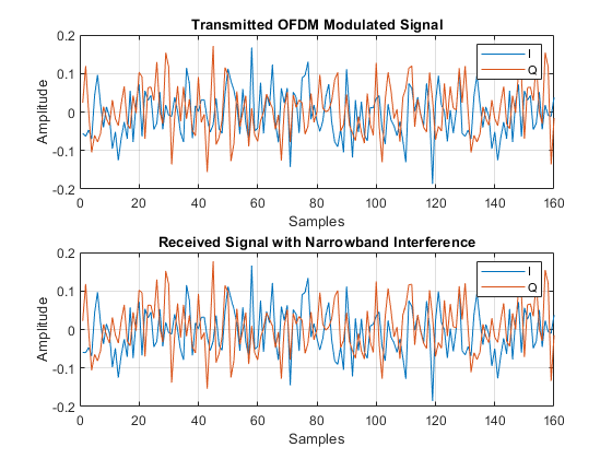
Pass the generated OFDM signal through an AWGN channel. The AGC scales the received signal to [-1 1] range. Pass the scaled signal through the bipolar ADC. Rescale the signal before applying OFDM and QAM demodulation. The narrowbandInterfererAndOFDM function simulates this system.
Run the simulation without interference. All the bits can be received without errors.
interfererAmp = 0;
ber = narrowbandInterfererAndOFDM(M,numSC,interfererAmp,numADCBits,SNR);
disp('BER:')
disp(ber)
BER:
     0

OFDM with ADC over AWGN Channel with High-Power Interferer
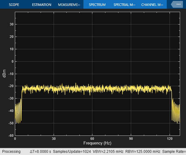
Use a tone to interfere with the 50th subcarrier of the OFDM signal. Set the amplitude of the interferer to 2 corresponding to an SIR value of about -28 dB. The high amplitude of the interfering signal forces the AGC to reduce its gain to avoid saturation. This scaling decreases the number of bits assigned to the desired signal and reduces the effective power of the desired signal. Quantization noise is a function of the fixed full-scale voltage and the number of bits properties of the ADC. As a result, the effective signal to noise ratio (SNR) decreases and the system starts to introduce bit errors.
interfererAmp = 2;
ber = narrowbandInterfererAndOFDM(M,numSC,interfererAmp,numADCBits,SNR);
disp('BER:')
disp(ber)
BER:
    0.0533


Effect of Adjacent Channel Users on a Multiuser System
Modern communication systems define multiple signal bandwidths to provide flexibility in choosing between highly reliable connections or high throughput. For example, 802.11 WLAN standard defines channel bandwidths that range from 20 MHz to 160 MHz. This figure shows the available WLAN channel bandwidths.

Typically, such systems are designed with fixed high bandwidth analog RF filters followed by programmable digital filters. An AGC and ADC combo is used to digitize the analog signal. If one of the users (i.e. channels) has much higher power than the rest of the users, the ADC quantization may cause a low SNR value for the low power users. The following demonstrates such a scenario.
Consider a Wi-Fi like system where there are eight independent transmitters (Device 1-8) and eight independent receivers (Device 1'-8'). Each transmitter-receiver pair is assigned one of the available 20 MHZ bands. 64-QAM modulated signals are OFDM modulated with 56 subcarriers in a bandwidth of 20 MHz. As shown in this figure, eight possible users are carried over channels 36, 40, 44, 48, 52, 56, 60, and 54, with corresponding carrier frequencies (5180:20:5320) MHz. The receivers employ analog filters that pass through the whole available 160 MHz band then use channelizer filters to select the desired user. To simplify the simulation, assume same path loss and thermal noise for each device pair. Also, the simulator uses the multiband combiner to combine signals from the eight users in the channel and channelizer to separate them in an efficient way. The dotted lines show the multiband combiner and channelizer.

M = 64;           % Modulation order per subcarrier
noiseFigure = 7;  % Noise figure in dB
numADCBits = 7;   % Number of ADC bits
Multiuser System with ADC over AWGN Channel
Generate OFDM modulated signals for all the active users and combine them using a comm.MultibandCombinermultiuserInterferenceAndADC function simulates this system.
Set all users as active with all users 0 dB relative gain. Run the simulation. All users operate without errors.
activeUsers = [1 1 1 1 1 1 1 1];
userGaindB = [0 0 0 0 0 0 0 0];

ber = multiuserInterferenceAndADC(M,noiseFigure,numADCBits,activeUsers,userGaindB);

disp('BER for each user:')
disp(ber)
BER for each user:
     0     0     0     0     0     0     0     0

Multiuser System with ADC over AWGN Channel with High Power User
Repeat the same experiment with a high-power user. Set the relative gain of the third user to 30 dB. Due to the decrease in the effective signal power as compared to the quantization noise (except the high-power user), the low power users experience bit errors and the BER performance degrades.
userGaindB = [0 0 30 0 0 0 0 0];
ber = multiuserInterferenceAndADC(M,noiseFigure,numADCBits,activeUsers,userGaindB);

disp('BER for each user:')
disp(ber)
BER for each user:
  Columns 1 through 7

    0.0386    0.0398         0    0.0425    0.0375    0.0393    0.0382

  Column 8

    0.0389

Further Exploration
The Narrowband Interferer and ADC Explorer app helps you quickly try different system settings to explore the effect of a high-power narrowband interferer on the system performance due to the fixed full-scale voltage and the quantization noise introduced by the ADC. Run NarrowbandInterfererAndADCExplorer, the Narrowband Interferer and ADC Explorer app.

Click "Simulation" switch to start the simulations.
Change "QAM Modulation order" to 16.
Increase the interferer amplitude to 4. Subcarrier 50 experiences interference by the narrowband interferer. "Bit errors in a Frame" gauge shows bit error between 0 and 4 bits since a single subcarrier is affected.
Reduce the "Number of ADC Bits" in and observe the received spectrum and bit errors in a frame. Around 7 bits, the ADC quantization errors start to degrade the system performance noticeably.
Experiment with different SNR and modulation order values and find out the limits of the system to handle a high-power narrowband interferer.
The Multiuser Interference and ADC Explorer app helps you quickly try different system settings to explore the effect of multiuser interference on the system performance due to the fixed full-scale voltage and the quantization noise introduced by the ADC. Run the Multiuser Interference and ADC Explorer app.

Click "Simulation" switch to start the simulations.
Change "QAM Modulation order" to 64.
Increase the gain of the 1st user to 40 dB.
Decrease the number of ADC bits in small steps. The noise floor in the received spectrum starts increasing. Around 10 bits, the low power users start to experience bit errors.
Reducing the number of ADC bits to 5, raises the noise floor above the signal level.