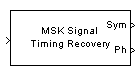
MSK-Type Signal Timing Recovery
Recover symbol timing phase using fourth-order nonlinearity method
Library
Timing Phase Recovery sublibrary of Synchronization
Description
The MSK-Type Signal Timing Recovery block recovers the symbol timing phase of the input signal using a fourth-order nonlinearity method. This block implements a general non-data-aided feedback method that is independent of carrier phase recovery but requires prior compensation for the carrier frequency offset. This block is suitable for systems that use baseband minimum shift keying (MSK) modulation or Gaussian minimum shift keying (GMSK) modulation.
Inputs
By default, the block has one input port. The input signal could be (but is not required to be) the output of a receive filter that is matched to the transmitting pulse shape, or the output of a lowpass filter that limits the amount of noise entering this block.
This block accepts a scalar-valued or column vector input signal. The input uses N samples to represent each symbol, where N > 1 is the Samples per symbol parameter.
For a column vector input signal, the block operates in single-rate processing mode. In this mode, the output signal inherits its sample rate from the input signal. The input length must be a multiple of N.
For a scalar input signal, the block operates in multirate processing mode. In this mode, the input and output signals have different sample rates. The output sample rate equals N multiplied by the input sample rate.
This block accepts input signals of type Double or Single
If you set the Reset parameter to On
nonzero input via port, then the block has a second
input port, labeled Rst. The Rst input
determines when the timing estimation process restarts, and must be
a scalar.
If the input signal is a scalar value, the sample time of the
Rstinput equals the symbol periodIf the input signal is a column vector, the sample time of the
Rstinput equals the input port sample timeThis block accepts reset signals of type Double or Boolean
Outputs
The block has two output ports, labeled Sym and Ph:
The
Symoutput is the result of applying the estimated phase correction to the input signal. This output is the signal value for each symbol, which can be used for decision purposes. The values in theSymoutput occur at the symbol rate:For a column vector input signal of length N*R, the
Symoutput is a column vector of length R having the same sample rate as the input signal.For a scalar input signal, the sample rate of the
Symoutput equals N multiplied by the input sample rate.
The
Phoutput gives the phase estimate for each symbol in the input.The
Phoutput contains nonnegative real numbers less than N. Noninteger values for the phase estimate correspond to interpolated values that lie between two values of the input signal. The sample time of thePhoutput is the same as that of theSymoutput.Note
If the
Phoutput is very close to either zero or Samples per symbol, or if the actual timing phase offset in your input signal is very close to zero, then the block's accuracy might be compromised by small amounts of noise or jitter. The block works well when the timing phase offset is significant rather than very close to zero.The output signal inherits its data type from the input signal.
Delays
When the input signal is a vector, this block incurs a delay of two symbols. When the input signal is a scalar, this block incurs a delay of three symbols.
Parameters
- Modulation type
The type of modulation in the system. Choices are
MSKandGMSK.- Samples per symbol
The number of samples, N, that represent each symbol in the input signal. This must be greater than 1.
- Error update gain
A positive real number representing the step size that the block uses for updating successive phase estimates. Typically, this number is less than 1/N, which corresponds to a slowly varying phase.
This parameter is tunable in normal mode, Accelerator mode and Rapid Accelerator mode. If you use the Simulink® Coder™ rapid simulation (RSIM) target to build an RSIM executable, then you can tune the parameter without recompiling the model. For more information, see Tunable Parameters (Simulink).
- Reset
Determines whether and under what circumstances the block restarts the phase estimation process. Choices are
None,Every frame, andOn nonzero input via port. The last option causes the block to have a second input port, labeledRst.
Algorithm
This block's algorithm extracts timing information by passing the sampled baseband signal through a fourth-order nonlinearity followed by a digital differentiator whose output is smoothed to yield an error signal. The algorithm then uses the error signal to make the sampling adjustments.
More specifically, this block uses a timing error detector whose result for the kth symbol is e(k), given in [2] by
where
r is the block's input signal
T is the symbol period
Ts is the sampling period
* means complex conjugate
dk is the phase estimate for the kth symbol
D is 1 for MSK and 2 for Gaussian MSK modulation
References
[1] D'Andrea, A. N., U. Mengali, and R. Reggiannini, "A Digital Approach to Clock Recovery in Generalized Minimum Shift Keying," IEEE Transactions on Vehicular Technology, Vol. 39, No. 3, August 1990, pp. 227-234.
[2] Mengali, Umberto and Aldo N. D'Andrea, Synchronization Techniques for Digital Receivers, New York, Plenum Press, 1997.
Version History
Introduced before R2006a