Bluetooth LE Channel Sounding for Asset Tracking
R2026bThis example shows how to estimate the position of a Bluetooth® low energy (LE) device by using channel sounding (CS) in the presence of interference. The simulation models ranging between locators and an asset device by using either round-trip time (RTT) or phase-based ranging (PBR), and then estimates the asset position from the measured distances. The example includes positions for both static and moving asset, models interference from a wireless local area network (WLAN) and Bluetooth nodes, and visualizes the estimated trajectory in a 3D scenario.
In this example, you:
Configure a Bluetooth LE tracking scenario with fixed locators, an asset device, and coexisting WLAN and Bluetooth interference nodes.
Model static and dynamic asset positions with configurable two-dimensional (2D) and three-dimensional (3D) motion trajectories.
Enable CS frequency hopping using channel selection algorithm (CSA) #3b for frequency diversity across packets.
Simulate CS exchanges by using either RTT or PBR-based ranging.
Model radio frequency (RF) impairments including carrier frequency offset (CFO), direct current (DC) offset, and indoor propagation path loss.
Estimate distance and position under configurable WLAN and Bluetooth interference conditions.
Visualize the spectrum and spectrogram of the Bluetooth LE signal in the presence of interference.
Track and visualize the trajectory and estimated positions of the asset in 3D.
Analyze positioning accuracy, packet success rate, and channel rejection rate under interference.
Technical Background
The Bluetooth Special Interest Group (SIG) [1] introduced Bluetooth LE CS [2]. Bluetooth® LE positioning uses CS to estimate distances between devices based on physical-layer (PHY) measurements. Compared to traditional received signal strength indicator (RSSI) based approaches, CS enables more accurate ranging by using timing and phase information from exchanged waveforms. For more information on Bluetooth CS, see What Is Bluetooth Channel Sounding?
Two commonly used distance estimation methods are:
RTT — RTT measures the time it takes for a signal to travel from the initiator to the reflector and back. By using the signal propagation speed, the system estimates the distance as half the RTT multiplied by the speed of light, while accounting for processing delays. To learn how to estimate the distance between Bluetooth LE devices by using RTT-based CS, see Estimate Distance Between Bluetooth LE Devices by Using Channel Sounding and Round-Trip Timing.
PBR — PBR uses the phase difference of received signals across multiple frequencies to estimate distance. By transmitting signals at different frequencies and analyzing the resulting phase shifts, the system resolves ambiguities and achieves higher accuracy. To learn how to estimate the distance between Bluetooth LE devices by using PBR-based CS, see Estimate Distance Between Bluetooth LE Devices by Using Channel Sounding and Phase-Based Ranging.
In this example, the simulation uses these methods within a Bluetooth LE tracking scenario to estimate distances between locators and an asset device. The example then uses these distance estimates to compute the asset position.
Both RTT and PBR methods are sensitive to channel conditions. In practical deployments, interference from coexisting WLAN and Bluetooth devices, as well as RF impairments and path loss, can degrade ranging accuracy and affect position estimates. This example models these effects to study system performance under realistic conditions.
Simulation Scenario
This example models an indoor Bluetooth LE tracking scenario in a 3D environment, as shown in this figure.
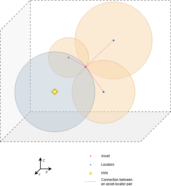
The scenario consists of:
Locator — Fixed Bluetooth LE devices with known positions
Asset — The device whose position you estimated
Interfering wireless nodes (IWNs) — WLAN and Bluetooth devices that introduce interference
The simulation deploys multiple Bluetooth LE locator nodes at fixed locations, while an asset device remains either static or moves along a predefined trajectory. WLAN and Bluetooth interference sources operate simultaneously, creating a realistic coexistence environment. For more information about coexistence between Bluetooth and WLAN, see Bluetooth-WLAN Coexistence.
As shown in the figure, the asset communicates with multiple locators using CS. Each locator covers a region around it. When the asset enters this region, the system estimates the distance between the asset and the locator by using either the RTT or PBR method. The system then computes the asset position from these distance measurements by using trilateration. For more information on trilateration, see Bluetooth Location and Direction Finding.
In this scenario, locators initiate a Bluetooth LE CS packet exchange procedure with the asset. The simulation models signal propagation by applying RF impairments and path loss. It introduces these effects:
Carrier frequency offset
Carrier phase offset
Timing drift
DC offset
Propagation path loss
This figure illustrates the CS packet exchange between a locator and the asset.
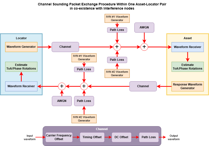
During each exchange, the system performs these operations:
Generate the CS waveform at the locator.
Generate WLAN and Bluetooth interfering waveforms.
Add propagation delay to the transmitted waveform.
Apply RF impairments and path loss.
Inject WLAN and Bluetooth interference.
Add additive white Gaussian noise (AWGN).
The asset receives the distorted waveform and processes it to estimate timing or phase information based on the selected ranging method. It then generates a response waveform, and the simulation applies the same propagation effects, impairments, and interference as the signal travels back to the locator.
The locator receives the response waveform and estimates the distance to the asset by using RTT or PBR. The system combines distance measurements from multiple locators and computes the asset position by using the blePositionEstimate function.
The simulation repeats this procedure for each asset position to track the asset trajectory over time. It then plots the estimated positions and trajectory in 2D or 3D space.
Configure Simulation Parameters
To ensure repeatability, initialize the random number generator with the default seed. To improve statistical accuracy, you can run the simulation with different seeds and average the results across multiple runs.
rng("default");Environment and Trajectory Configuration
Set the simulation environment, asset trajectory, motion model, and room dimensions. You can specify the environment model as "Outdoor", "Industrial", "Home", or "Office". You can specify the asset trajectory as "Circular Path", "Fixed Path", "Linear Path", or "Random Path". You can specify the motion model as "2-D Constant Velocity", "3-D Constant Velocity", "2-D Constant Acceleration", or "3-D Constant Acceleration". This example uses a circular trajectory and a three-dimensional constant-velocity motion model.
environmentModel ="Office"; trajectory =
"Circular Path"; motionModel =
"3-D Constant Velocity"; roomSize =
[50 40 30]; % In x-, y-, and z-coordinates. Units are in meters.
Set the bit energy-to-noise density ratio (Eb/No) and propagation speed.
EbNo =24; % Eb/No in dB speedOfLight = physconst("LightSpeed");% Speed of light in m/s
Bluetooth LE CS Configuration
Set the PHY mode and CS step mode. You can specify the PHY mode as "LE1M", "LE2M", or "LE2M 2BT". You can specify the CS step mode as 1 or 2, corresponding to CS SYNC and CS tone exchange, respectively. This example uses the step mode 2.
phyMode ="LE2M"; csStepMode =
2;
Set the CS tone duration, optional sequence type, sounding sequence length, device roles, and waveform sampling frequency. You can specify the tone duration as 10, 20, or 40 microseconds. You can specify the sounding sequence length as 32 or 96. This example uses the "Sounding Sequence" as the sequence type.
toneDuration =40; % In microseconds sequenceType = "Sounding Sequence"; sequenceLength =
96; deviceRoles = ["Initiator","Reflector"]; sampleRate = 80e6;
IWN Configuration
Enable or disable interference from coexisting wireless nodes (WLAN and Bluetooth LE). When you enable interference, the simulation generates interfering waveforms, injects them into the received signal, and applies a receiver channel filter to suppress out-of-band energy. When you disable interference, the simulation models a clean channel with only RF impairments, path loss, and AWGN.
enableInterference =  "On";
"On";Enable or disable frequency hopping. When you enable frequency hopping, the simulation uses CS channel selection algorithm (CSA) #3b with per-procedure hopping. When you disable frequency hopping, the simulation uses the same fixed contiguous block of channels for every packet.
enableFrequencyHopping =  "On";
"On";Configure the IWNs. Each IWN specifies a signal type, transmitter position, operating frequency, transmitter power, and collision probability. A collision probability in the range [0,1] controls temporal overlap with the Bluetooth LE signal. A value between 0 and 1 models partial collision, a value of 1 models full collision, and a value of 0 disables interference.
To add WLAN interference by using different WLAN signal types, you must have WLAN Toolbox™. If you do not have WLAN Toolbox, set the SignalType property of an iwn element to WLANBasebandFile. Because WLANBasebandFile captures data in a single-input single-output (SISO) configuration, set NumWLANTransmitAntennas to 1.
Initialize the IWN count. If you disable the interference, you can skip this section.
if enableInterference == "On" % Define the first interference node as a WLAN high efficiency (HE) % single-user (SU) signal at 2437 MHz. This WLAN signal has 20 MHz % bandwidth centered at channel 6 and overlaps with Bluetooth LE CS % channels 26–44 (2428–2446 MHz). k = 0; k = k+1; iwn(k).SignalType ="WLANHESUBandwidth20.bb"; iwn(k).TxPosition =
[20,0,2]; % In meters[15,20,5]; iwn(k).Frequency = 2437e6; % In Hz iwn(k).NumWLANTransmitAntennas = 1; % Number of transmit antennas relevant for WLAN signals iwn(k).TxPower = 20; % In dBm iwn(k).CollisionProbability =
0.7; % Probability of collision in time, must be between [0,1] iwn(k).WLANOverSamplingFactor = 1; % Over sampling factor relevant for WLAN signals % Define the second interference node as a Bluetooth LE1M signal at % 2408 MHz. k = k+1; iwn(k).SignalType =
"LE1M"; iwn(k).TxPosition =
[6,7,5]; % In meters iwn(k).Frequency = 2408e6; % In Hz iwn(k).TxPower = 20; % In dBm iwn(k).CollisionProbability =
0.3; % Probability of collision in time, must be between [0,1] % Create and configure the IWN by using the helperIWNConfig helper object. iwnConfig = helperIWNConfig(IWN=iwn,SampleRate=sampleRate, ... Environment=environmentModel); end
Specify the full pool of allowed Bluetooth LE CS channels. Per Bluetooth Core Specification v6.3 [2], Vol 6, Part H, Section 1, channel indices 0, 1, 23, 24, 25, 77, and 78 are prohibited. Consequently, 72 channels are allowed and they span 2404–2424 MHz and 2428–2478 MHz with 1 MHz spacing. Use the full 72-channel pool. The hopping sequence is generated once per CS procedure and then stepped through packet by packet. This hopping sequence provides frequency diversity across the available spectrum while preserving the contiguous channel structure required by the ranging procedure.
allowedCSChannelIndices = [2:22 26:76];
allowedChannelFrequencies = (2402 + allowedCSChannelIndices) * 1e6;
numCSChannels = numel(allowedChannelFrequencies);
Compute the symbol rate from the selected PHY mode, and then compute the number of samples per symbol.
if phyMode == "LE1M"
    symbolRate = 1e6;
else
    symbolRate = 2e6;
end

samplesPerSymbol = sampleRate/symbolRate;
Compute the receiver matched-filter decimation factor, the post-decimation sample rate and the number of samples per symbol. When interference is enabled, the receiver combines a lowpass matched filter with downsampling to suppress out-of-band interference and reduce the sample rate feeding the estimator.
if samplesPerSymbol > 16
    decimationFactor = sampleRate/16e6;
else
    decimationFactor = 1;
end
rxSamplesPerSymbol = samplesPerSymbol/decimationFactor;
rxSampleRate = sampleRate/decimationFactor;
Convert Eb/No to SNR for waveform-level simulation, and set the transmitter power.
snr = EbNo - 10*log10(samplesPerSymbol); txPower =20; % In dBm dBmToWattOffset = 30; % dBm-to-watt conversion offset
Create and configure the Bluetooth LE CS waveform configuration object.
cfgChannelSoundingTx = bleCSConfig(StepMode=csStepMode, ...
    SamplesPerSymbol=samplesPerSymbol, ...
    Mode=phyMode, ...
    ToneDuration=toneDuration, ...
    SequenceLength=sequenceLength, ...
    SequenceType=sequenceType, ...
    OutputDataType="double");
Create and configure the Bluetooth LE CS waveform configuration object for the receiver and set the number of samples per symbol.
cfgChannelSoundingRx = cfgChannelSoundingTx;
cfgChannelSoundingRx.SamplesPerSymbol = rxSamplesPerSymbol;
Network Topology and Locator Deployment
Set the packet-level simulation limits and determine the number of spatial dimensions from the selected motion model.
maxNumPackets = 15;    % Maximum number of packets simulated per ranging procedure
minValidPackets = 10;  % Minimum number of valid packets required for a reliable estimate

numDimensions = 2 + any(motionModel == ["3-D Constant Velocity","3-D Constant Acceleration"]);
Validate the number of dimensions implied by the selected motion model.
if numDimensions > 3
    error("To estimate 3-D position of the asset, room size must be a three-element column.")
end
if numDimensions < 2
    error("To estimate 2-D position of the asset, room size must be a two-element column.")
end
Set the number of locators and asset positions, and then generate their coordinates from the motion model and trajectory using the helperBLEPositions helper function.
numLocators = 15;
numPositionsAsset = 8;

[posAsset,posLocators] = helperBLEPositions(motionModel,numPositionsAsset,numLocators,roomSize,trajectory);
Preallocate memory for the estimated asset positions and the active locator positions used at each asset location.
posAssetEstimate = zeros(numDimensions,numPositionsAsset);
posLocatorBuffer = cell(1,numPositionsAsset);
Create an FIR lowpass filter to serve as the matched filter for the LE CS waveform.
lpFilter = designfilt("lowpassfir", ...
    FilterOrder=32, ...
    CutoffFrequency=rxSampleRate/2 * 0.8, ...
    SampleRate=sampleRate);
filterDelay = mean(grpdelay(lpFilter));
RF Impairment Configuration
Create the variable fractional delay object by using the dsp.VariableFractionalDelay (DSP System Toolbox) System object™.
timingDelay = dsp.VariableFractionalDelay;
To configure the RF impairments, use the helperBLEImpairmentsInit helper object.
initImp = helperBLEImpairmentsInit(phyMode,samplesPerSymbol);
Create and configure the coarse frequency compensator used by the receiver. Use post-decimation rates for the compensator when interference is enabled. Otherwise use the transmit rates.
compensatorSampleRate = rxSampleRate;
compensatorSamplesPerSymbol = rxSamplesPerSymbol;
Create and configure the coarse frequency compensator used by the receiver.
if csStepMode == 1
    % Specify modulation type as orthogonal quadrature phase shift keying
    % (OQPSK) for CS step mode 1 with GFSK modulation scheme.
    freqCompensator = comm.CoarseFrequencyCompensator(Modulation="OQPSK", ...
        SampleRate=compensatorSampleRate, ...
        SamplesPerSymbol=compensatorSamplesPerSymbol, ...
        FrequencyResolution=200);
else
    % Specify modulation type as quadrature amplitude modulation (QAM) for
    % CS step mode 2 with ASK modulation scheme.
    freqCompensator = comm.CoarseFrequencyCompensator(Modulation="QAM", ...
        SampleRate=compensatorSampleRate, ...
        FrequencyResolution=200);
end
Create the path-loss configuration object and initialize the random stream index used across asset positions and locators.
cfgPathLoss = bluetoothPathLossConfig(Environment=environmentModel);
countStream = 1;
Set the number of CS channels used in each packet exchange. Then compute the valid contiguous block start indices within the allowed channel pool. A valid start index must produce a block of numChannelsPerPacket consecutive channels with 1 MHz spacing and no prohibited-channel gap. This constraint preserves phase linearity for PBR.
numChannelsPerPacket = 2;
channelSpacing = diff(allowedChannelFrequencies);
validBlockStartIndices = find(arrayfun(@(s) all(channelSpacing(s:s+numChannelsPerPacket-2) == 1e6), ...
    1:(numCSChannels - numChannelsPerPacket + 1)))';
Run Coexistence Simulation and Visualize Results
For all the generated asset positions, simulate the motion of the asset and estimate its position by performing the CS packet exchange procedure in the presence of WLAN and Bluetooth LE interference.
Preallocate memory to store per-position quality metrics.
packetSuccessRate = zeros(1,numPositionsAsset);
qualityRejectionRate = zeros(1,numPositionsAsset);
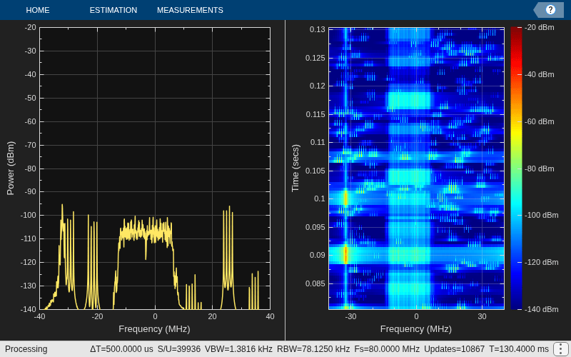
Create and configure the spectrum analyzer to visualize the spectrum and spectrogram of the Bluetooth LE Channel Sounding waveform in the presence of interference. The spectrum analyzer is only created when interference is enabled.
if enableInterference == "On"
    specAn = spectrumAnalyzer(...
        Name="Bluetooth Coexistence Modeling", ...
        ViewType="Spectrum and spectrogram", ...
        TimeResolutionSource="Property", ...
        TimeResolution=0.0005, ...
        SampleRate=sampleRate, ...
        TimeSpanSource="Property", ...
        TimeSpan=0.05, ...
        FrequencyResolutionMethod="num-frequency-bands", ...
        FFTLengthSource="property", ...
        AxesLayout="Horizontal", ...
        YLimits=[-140 -20], ...
        ColorLimits=[-140 -20]);
end
Display information about the simulation.
fprintf("Running Simulation for Interference: %s, Frequency Hopping: %s, CS Mode: %d, PHY: %s \n", ...
    enableInterference,enableFrequencyHopping,csStepMode,phyMode);
Running Simulation for Interference: On, Frequency Hopping: On, CS Mode: 2, PHY: LE2M
For all the generated asset positions, simulate the motion of the asset.
for countPositionAsset = 1:numPositionsAssetConfigure the nearest active locators to the asset.
[posActiveLocators,~,distanceActive] = helperBLEActiveLocators(posAsset(:,countPositionAsset),posLocators,"lateration");Compute the number of active locators.
numActiveLocators = size(posActiveLocators,2);
Preallocate the space to store the measured distance values.
distanceMeasured = zeros(1,numActiveLocators);
Update the buffer of active locator positions.
posLocatorBuffer{:,countPositionAsset} = posActiveLocators;Estimate the path loss between each locator and the asset, based on the simulation environment and the distance between them, by using the bluetoothPathLoss function.
pathlossLinear = 10.^(bluetoothPathLoss(distanceActive,cfgPathLoss)/20);
Generate IWN waveforms by using the generateIWNWaveform object function. This step is skipped when interference is disabled.
    assetPosition = posAsset(:,countPositionAsset);
    if enableInterference == "On"
        iwnWaveform = generateIWNWaveform(iwnConfig);
        iwnConfigTrimmed = iwnConfig;
        if numDimensions==2
            for countIWN = 1:numel(iwnConfigTrimmed.IWN)
                iwnConfigTrimmed.IWN(countIWN).TxPosition = iwnConfigTrimmed.IWN(countIWN).TxPosition(1:2);
            end
        end
    end
Initialize per-position quality tracking variables.
    totalPacketsAttempted = 0;
    totalPacketsValid = 0;
    totalChannelAttempts = 0;
    totalChannelRejections = 0;
Loop over the active locators only.
for countLocators = 1:numActiveLocatorsTo ensure that each iteration uses a repeatable set of random numbers, set a different substream for each iteration.
        stream = RandStream("combRecursive");
        stream.Substream = countStream;
        RandStream.setGlobalStream(stream)
Get the distance (in meters) between the asset and the locator.
distance = distanceActive(countLocators);
Specify the device position for the path-loss model.
devicePosition = [assetPosition(:),posActiveLocators(:,countLocators)];
Compute the waveform propagation time (in seconds) between the devices.
propagationTime = distance/speedOfLight;
Specify the initial phases (in radians) of the initiator and the reflector.
        initialPhaseInitiator = rand*pi/4;
        initialPhaseReflector = rand*pi/4;
Preallocate the space to store the estimated distance values.
estimatedDistance = zeros(maxNumPackets,1);
Specify the delay structure for the Bluetooth LE CS waveform.
        delayStructure = struct(propagationTime=propagationTime, ...
            Fc=0, ...
            timingDelayVFD=timingDelay, ...
            phi0=initialPhaseInitiator-initialPhaseReflector, ...
            sampleRate=sampleRate, ...
            sps=samplesPerSymbol);
Initialize the valid packet counter.
validPacketCount = 0;
Compute the signal of interest (SOI) amplitude after applying the transmitter power and path loss.
soiAmplitudeLinear = 10^((txPower - dBmToWattOffset)/20)/pathlossLinear(countLocators);
Generate the channel hopping sequence for this CS procedure. When frequency hopping is enabled, CSA #3b shuffles the valid contiguous-block start indices. Each packet selects the next start index from the shuffled sequence to select a contiguous block of numChannelsPerPacket channels—preserving phase linearity for PBR while providing frequency diversity across packets.
        if enableFrequencyHopping == "On"
            shuffledBlockStarts = helperBLECSChannelSelection3b(validBlockStartIndices);
            hoppingIndex = 0;
        end
Simulate each Bluetooth LE CS packet by performing the CS packet exchange procedure.
for countPacket = 1:maxNumPacketsInitialize the round-trip measurement variable for time and phase per channel for both step modes.
            roundTripMetricChannel = zeros(1,numChannelsPerPacket);
            channelValid = true(1,numChannelsPerPacket);
Specify the packet as valid before analysis.
packetValid = true;
Select channels for this packet.
            if enableFrequencyHopping == "On"
                if hoppingIndex >= numel(shuffledBlockStarts)
                    shuffledBlockStarts = helperBLECSChannelSelection3b(validBlockStartIndices);
                    hoppingIndex = 0;
                end
                hoppingIndex = hoppingIndex + 1;
                startIdx = shuffledBlockStarts(hoppingIndex);
                packetFrequencies = allowedChannelFrequencies(startIdx:startIdx+numChannelsPerPacket-1);
            else
                packetFrequencies = allowedChannelFrequencies(1:numChannelsPerPacket);
            end
Increment the packet and channel attempt counters.
            totalPacketsAttempted = totalPacketsAttempted + 1;
            totalChannelAttempts = totalChannelAttempts + numChannelsPerPacket;
Configure the RF impairment.
            initImp.pfo.FrequencyOffset = randi([-150e2,150e2])*10; % Frequency offset in Hz, range is [-150000,+150000]
            initImp.pfo.PhaseOffset = randi([-2,2])*5;              % Phase offset in degrees
            initImp.vdelay = 0;                                     % Variable timing offset
            initImp.dc = 5;                                         % Percentage related to maximum amplitude value
Loop over the CS channels in this packet.
for countChannel = 1:numChannelsPerPacketGet the carrier frequency for this channel.
delayStructure.Fc = packetFrequencies(countChannel);
Initialize the per-channel variable for the time of arrival (ToA) and phase rotation measurements.
measurementDevice = zeros(1,2);
Loop over the initiator and reflector device roles.
                for countDevice = 1:2
                    cfgChannelSoundingTx.DeviceRole = deviceRoles(countDevice);
Generate the Bluetooth LE CS waveform by using the bleCSWaveform function.
[txWaveform,accessAddress] = bleCSWaveform(cfgChannelSoundingTx);
Add the RF impairment to the generated Bluetooth LE waveform.
txImpairedWfm = helperBLEImpairmentsAddition(txWaveform,initImp);
Add propagation delay to the generated Bluetooth LE CS waveform.
delayWaveform = addPropagationDelay(txImpairedWfm,delayStructure,csStepMode,countDevice);
Scale the waveform as per the transmitter power and path loss.
attenuatedWaveform = soiAmplitudeLinear*delayWaveform;
Apply interference (if enabled), shift to baseband, add AWGN, and filter.
                    if enableInterference == "On"
                        % Add path loss to IWN waveforms based on
                        % environment and node positions.
                        [iwnWaveformWithPathloss,~] = applyPathloss(iwnConfigTrimmed,iwnWaveform,devicePosition(:,countDevice)');

                        % Combine Bluetooth LE SOI with path-loss-
                        % attenuated IWN waveforms.
                        combinedWaveform = addInterference(iwnConfigTrimmed, ...
                            attenuatedWaveform,iwnWaveformWithPathloss,delayStructure.Fc);

                        % Shift combined waveform to baseband.
                        freqShiftedWaveform = frequencyOffset(combinedWaveform,sampleRate,2440e6-delayStructure.Fc);

                        % Compute AWGN power relative to SOI to avoid noise
                        % when interference is present.
                        soiPower = 20*log10(soiAmplitudeLinear);
                        noisePower = soiPower - snr;
                        signalPlusInterferenceToNoise = 10*log10(var(freqShiftedWaveform)) - noisePower;
                        noisyWaveform = awgn(freqShiftedWaveform,signalPlusInterferenceToNoise,"measured");
                    else
                        % Add AWGN to the attenuated waveform.
                        noisyWaveform = awgn(attenuatedWaveform,snr,"measured");
                    end

                    % Pad the noisy waveform and apply the combined matched
                    % filter and decimator.
                    paddedWaveform = [noisyWaveform;zeros(filterDelay,1)];
                    filteredWaveform = filter(lpFilter,paddedWaveform);
                    trimmedWaveform = filteredWaveform(filterDelay+1:end);
                    rxWaveform = downsample(trimmedWaveform,decimationFactor);
Estimate the ToA for step mode 1 and the phase rotation for step mode 2.
[measuredParam,qIndex] = estimateParams(rxWaveform,cfgChannelSoundingRx,accessAddress,freqCompensator);
If the quality index indicates failure, mark this channel as invalid.
                    if qIndex  % Bad quality - skip this channel
                        channelValid(countChannel) = false;
                        totalChannelRejections = totalChannelRejections + 1;
                        break
                    else
                        % Store the phase rotation or ToA measurement based on the CS step mode.
                        measurementDevice(countDevice) = measuredParam;
                    end
                end
Accumulate the round-trip measurements for valid channels.
roundTripMetricChannel(countChannel) = measurementDevice(1) + measurementDevice(2);
Visualize the spectrum and spectrogram for each channel to show the frequency hopping pattern. Each call adds a time slice at the current carrier frequency.
                if enableInterference == "On"
                    specAn(combinedWaveform)
                end
            end
Convert the round-trip measurements to distance. For step mode 1 (RTT), pass the round-trip time calculations and for step mode 2 (PBR), pass the accumulated phase rotations and carrier frequencies. Both paths require at least one valid channel for RTT or two for PBR.
            validIdx = find(channelValid);
            if numel(validIdx) >= 2
                estimatedDistance(countPacket) = helperBLEDistanceEstimate(roundTripMetricChannel(validIdx), ...
                    packetFrequencies(validIdx),csStepMode);
                validPacketCount = validPacketCount + 1;
                totalPacketsValid = totalPacketsValid + 1;
            else
                packetValid = false;
            end
Stop if the minimum number of valid packets has been reached.
            if validPacketCount >= minValidPackets
                break
            end
        end
Increment the random stream count by 1.
countStream = countStream + 1;
Apply median-based rejection by discarding estimates more than 2 m from the median.
        validRows = estimatedDistance ~= 0;
        if any(validRows)
            validDistances = estimatedDistance(validRows);
            medianDistance = median(validDistances);
            inliers = abs(validDistances - medianDistance) < 2;
            if any(inliers)
                averageDistance = mean(validDistances(inliers));
            else
                averageDistance = medianDistance;
            end
Apply a room-diagonal bound.
            maxRoomDist = norm(roomSize);
            if averageDistance <= maxRoomDist && averageDistance > 0
                distanceMeasured(countLocators) = averageDistance;
            end
        end
    end
Record the per-position quality metrics.
    if totalPacketsAttempted > 0
        packetSuccessRate(countPositionAsset) = totalPacketsValid / totalPacketsAttempted * 100;
        qualityRejectionRate(countPositionAsset) = totalChannelRejections / totalChannelAttempts * 100;
    end
Filter out locators with no valid measurement before trilateration.
    validMask = distanceMeasured > 0;
    minLocatorsNeeded = numDimensions + 3;
    if sum(validMask) >= minLocatorsNeeded
        activePosition = posActiveLocators(:,validMask);
        activeDistance = distanceMeasured(validMask);
    else
        activePosition = posActiveLocators;
        activeDistance = distanceMeasured;
    end
Estimate the position of the asset by using the trilateration method.
posAssetEstimate(:,countPositionAsset) = blePositionEstimate(activePosition,"lateration",activeDistance);Display simulation progress.
    fprintf(" Position %d/%d: Average Error = %.2f m, Packet success = %.0f%% and Channel reject = %.0f%% \n", ...
        countPositionAsset,numPositionsAsset, ...
        norm(posAssetEstimate(:,countPositionAsset) - posAsset(:,countPositionAsset)), ...
        packetSuccessRate(countPositionAsset), ...
        qualityRejectionRate(countPositionAsset));
end
 Position 1/8: Average Error = 0.09 m, Packet success = 89% and Channel reject = 11%
 Position 2/8: Average Error = 0.13 m, Packet success = 84% and Channel reject = 15%
 Position 3/8: Average Error = 0.19 m, Packet success = 90% and Channel reject = 9%
 Position 4/8: Average Error = 0.93 m, Packet success = 67% and Channel reject = 32%
 Position 5/8: Average Error = 3.23 m, Packet success = 67% and Channel reject = 30%
 Position 6/8: Average Error = 1.45 m, Packet success = 62% and Channel reject = 36%
 Position 7/8: Average Error = 0.43 m, Packet success = 92% and Channel reject = 8%
 Position 8/8: Average Error = 0.63 m, Packet success = 88% and Channel reject = 10%
Compute the position estimation error for each asset position.
posError = vecnorm(posAssetEstimate - posAsset);
csMethod = ["RTT","PBR"];
Display the average positioning error.
fprintf("\nAverage positioning error: %.3f meters by using the %s method with Frequency hopping: %s\n", ...
    mean(posError),csMethod(csStepMode),enableFrequencyHopping);
Average positioning error: 0.885 meters by using the PBR method with Frequency hopping: On
Visualize Asset Tracking with Interference Overlay
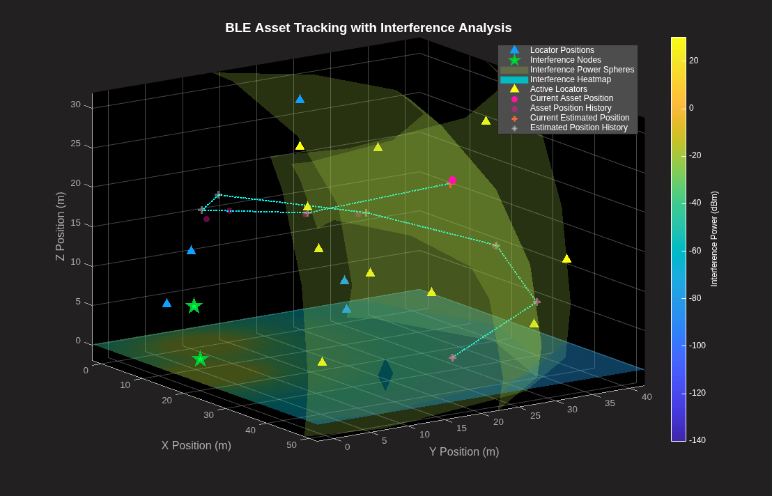
Visualize the estimated and actual asset trajectory in 3D using the helperBLEVisualizeNodeTracking helper function. The function animates the asset movement, plotting actual positions, estimated positions, and locators. When enabled, it overlays interference nodes as green stars with power spheres colored by received power, and renders a 2D interference heatmap across the environment. The plot supports interactive rotation, panning, and zooming.
if ~all(isnan(posAssetEstimate(1,:)))
    if enableInterference == "On"
        visualOptions = struct(showInterferenceNodes=1, ...
            showInterferencePowerSpheres=1, ...
            showInterferenceHeatmap=1, ...
            showLocalizationSpheres=0, ...
            showTrajectory=1, ...
            animationSpeed=0.75, ...
            IWNConfig=iwnConfig);
    else
        visualOptions = struct(showInterferenceNodes=0, ...
            showInterferencePowerSpheres=0, ...
            showInterferenceHeatmap=0, ...
            showLocalizationSpheres=0, ...
            showTrajectory=1, ...
            animationSpeed=0.75);
    end
    helperBLEVisualizeNodeTracking(posLocators,posAsset, ...
        posLocatorBuffer,posAssetEstimate, ...
        roomSize,visualOptions)
end
Supporting Functions
The example uses these helper functions.
helperBLEActiveLocators.m— Generate active locator parameters.helperBLECSChannelSelection3b.m— Shuffle channel frequency with CSA #3b frequency hopping.helperBLEDistanceEstimate.m— Estimate distance using multi-channel PBR phase or round trip time.helperBLEPhaseEstimate.m— Estimate the time of arrival of the Bluetooth LE CS Tone waveform using PBR.helperBLEPositions.m— Generate locators and asset positions.helperBLETOAEstimate.m— Estimate the time of arrival of the Bluetooth LE CS SYNC waveform using RTT.helperBLEVisualizeNodeTracking.m— Generate Bluetooth LE asset tracking visualization.helperIWNConfig.m— Configure interference wireless node parameters.
References
[1] Bluetooth Technology Website. "Bluetooth Technology Website | The Official Website of Bluetooth Technology." Accessed May 22, 2026. https://www.bluetooth.com/.
[2] Bluetooth Core Specifications Working Group. "Bluetooth Core Specification" v6.3. https://www.bluetooth.com/specifications/specs/core-specification-6-3/.
[3] Bluetooth Range Estimator. "Path Loss (Propagation) Models." Bluetooth Special Interest Group (SIG). https://www.bluetooth.com.
%% Local Functions

function [measuredParam,qIndex] = estimateParams(rxWaveform,cfgCS,accessAddress,freqCompensator)
% estimateDistance Estimate the distance from the received CS waveform.
%   Removes DC offset and compensates for carrier frequency offset, then
%   estimates either time of arrival (ToA) or phase rotations depending on
%   the CS step mode.

% Remove DC offset from the received waveform.
rxDCFree = rxWaveform - mean(rxWaveform);
correctedWaveform = zeros(size(rxDCFree));

% Compensate for carrier frequency offset.
for countColumn = 1:width(rxDCFree)
    correctedWaveform(:,countColumn) = freqCompensator(rxDCFree(:,countColumn));
    release(freqCompensator)
end

if cfgCS.StepMode == 1
    % Estimate time of arrival for CS step mode 1
    [measuredParam,qualityValue] = helperBLETOAEstimate(correctedWaveform,cfgCS,accessAddress);

    % Assign quality index for non-zero quality value
    qIndex = (qualityValue ~= 0);
elseif cfgCS.StepMode == 2
    % Estimate the phase rotations for two channels
    [measuredParam,qIndex] = helperBLEPhaseEstimate(correctedWaveform,cfgCS);
end
end

function waveformOut = addPropagationDelay(waveformIn,impairments,stepMode,countDeviceRole)
% addPropagationDelay Add propagation delay to the CS waveform.
%   For Mode-1, adds a timing delay using the variable fractional delay
%   object. For Mode-2, applies a phase rotation corresponding to the
%   propagation time.

% Specify the samples per symbol
sps = impairments.sps;

if stepMode == 1
    % Specify the number of samples to delay
    samplesToDelay = cast(impairments.propagationTime*(impairments.sampleRate),class(waveformIn));

    % Add propagation delay to the waveform
    waveformOut = impairments.timingDelayVFD( ...
        [waveformIn; zeros((ceil(samplesToDelay/sps))*sps,1)],samplesToDelay);

    reset(impairments.timingDelayVFD);
else
    % Specify the phase delay
    phaseToDelay = (2*pi*impairments.Fc)*impairments.propagationTime;

    % Delay the waveform with phase
    waveformOut = waveformIn*exp(1j*(-phaseToDelay))*exp((-1j)*(-1)^countDeviceRole*(impairments.phi0));
end
end

