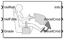
Main Content

Longitudinal Driver

Longitudinal speed-tracking controller

  • Longitudinal Driver block

Libraries:
Powertrain Blockset / Vehicle Scenario Builder
Vehicle Dynamics Blockset / Vehicle Scenarios / Driver

Description

The Longitudinal Driver block implements a longitudinal speed-tracking controller. Based on reference and feedback velocities, the block generates normalized acceleration and braking commands that can vary from 0 through 1. You can use the block to model the dynamic response of a driver or to generate the commands necessary to track a longitudinal drive cycle.

Configurations

External Actions

Use the External Actions parameters to create input ports for signals that can disable, hold, or override the closed-loop acceleration or deceleration commands. The block uses this priority order for the input commands: disable (highest), hold, override.

This table summarizes the external action parameters.

Goal

External Action Parameter

Input Ports

Data Type

Override the accelerator command with an input acceleration command.

Accelerator override

EnablAccelOvr

Boolean

AccelOvrCmd

double

Hold the acceleration command at the current value.

Accelerator hold

AccelHldBoolean

Disable the acceleration command.

Accelerator disable

AccelZeroBoolean

Override the decelerator command with an input deceleration command.

Decelerator override

EnablDecelOvr

Boolean

DecelOvrCmd

double

Hold the decelerator command at current value.

Decelerator hold

DecelHldBoolean

Disable the decelerator command.

Decelerator disable

DecelZeroBoolean

Controller

Use the Control type, cntrlType parameter to specify one of these control options.

Setting

Block Implementation

PI

Proportional-integral (PI) control with tracking windup and feed-forward gains.

Scheduled PI

PI control with tracking windup and feed-forward gains that are a function of vehicle velocity.

Predictive

Optimal single-point preview (look ahead) control model developed by C. C. MacAdam1, 2, 3. The model represents driver steering control behavior during path-following and obstacle avoidance maneuvers. Drivers preview (look ahead) to follow a predefined path. To implement the MacAdam model, the block:

  • Represents the dynamics as a linear single track (bicycle) vehicle

  • Minimizes the previewed error signal at a single point T* seconds ahead in time

  • Accounts for the driver lag deriving from perceptual and neuromuscular mechanisms

Shift

Use the Shift type, shftType parameter to specify one of these shift options.

Setting

Block Implementation

None

No transmission. Block outputs a constant gear of 1.

Use this setting to minimize the number of parameters you need to generate acceleration and braking commands to track forward vehicle motion. This setting does not allow reverse vehicle motion.

Reverse, Neutral, Drive

Block uses a Stateflow® chart to model reverse, neutral, and drive gear shift scheduling.

Use this setting to generate acceleration and braking commands to track forward and reverse vehicle motion using simple reverse, neutral, and drive gear shift scheduling. Depending on the vehicle state and vehicle velocity feedback, the block uses the initial gear and time required to shift to shift the vehicle up into drive or down into reverse or neutral.

For neutral gears, the block uses braking commands to control the vehicle speed. For reverse gears, the block uses an acceleration command to generate torque and a brake command to reduce vehicle speed.

Scheduled

Block uses a Stateflow chart to model reverse, neutral, park, and N-speed gear shift scheduling.

Use this setting to generate acceleration and braking commands to track forward and reverse vehicle motion using reverse, neutral, park, and N-speed gear shift scheduling. Depending on the vehicle state and vehicle velocity feedback, the block uses these parameters to determine the:

  • Initial gear

  • Upshift and downshift accelerator pedal positions

  • Upshift and downshift velocity

  • Timing for shifting and engaging forward and reverse from neutral

For neutral gears, the block uses braking commands to control the vehicle speed. For reverse gears, the block uses an acceleration command to generate torque and a brake command to reduce vehicle speed.

External

Block uses the input gear, vehicle state, and velocity feedback to generate acceleration and braking commands to track forward and reverse vehicle motion.

For neutral gears, the block uses braking commands to control the vehicle speed. For reverse gears, the block uses an acceleration command to generate torque and a brake command to reduce vehicle speed.

Gear Signal

Use the Output gear signal parameter to create the GearCmd output port. The GearCmd signal contains the integer value of the commanded vehicle gear.

Gear

Integer

Park

80

Reverse

-1

Neutral

0

Drive

1

Gear

Gear number

Controller: PI Speed-Tracking

If you set the control type to PI or Scheduled PI, the block implements proportional-integral (PI) control with tracking windup and feed-forward gains. For the Scheduled PI configuration, the block uses feed forward gains that are a function of vehicle velocity.

To calculate the speed control output, the block uses these equations.

Setting

Equation

PI

y=Kffvnomvref+Kperefvnom+(Kierefvnom+Kaweout)dt+Kgθ

Scheduled PI

y=Kff(v)vnomvref+Kp(v)erefvnom+(Ki(v)erefvnom+Kaweout)dt+Kg(v)θ

where:eref=vrefveout=ysatyysat={1y<1y1y111<y

The velocity error low-pass filter uses this transfer function.

H(s)=1τerrs+1   for   τerr>0

To calculate the acceleration and braking commands, the block uses these equations.

yacc={0ysat<0ysat0ysat111<ysatydec={0ysat>0ysat1ysat01ysat<1

The equations use these variables.

vnom

Nominal vehicle speed

Kp

Proportional gain

Ki

Integral gain

Kaw

Anti-windup gain

Kff

Velocity feed-forward gain

Kg

Grade angle feed-forward gain

θ

Grade angle

τerr

Error filter time constant

y

Nominal control output magnitude

ysat

Saturated control output magnitude

eref

Velocity error

eout

Difference between saturated and nominal control outputs

yacc

Acceleration signal

ydec

Braking signal

v

Velocity feedback signal

vref

Reference velocity signal

Controller: Predictive Speed-Tracking

If you set the Control type, cntrlType parameter to Predictive, the block implements an optimal single-point preview (look ahead) control model developed by C. C. MacAdam1, 2, 3. The model represents driver steering control behavior during path-following and obstacle avoidance maneuvers. Drivers preview (look ahead) to follow a predefined path. To implement the MacAdam model, the block:

  • Represents the dynamics as a linear single track (bicycle) vehicle

  • Minimizes the previewed error signal at a single point T* seconds ahead in time

  • Accounts for the driver lag deriving from perceptual and neuromuscular mechanisms

Vehicle Dynamics

For longitudinal motion, the block implements these linear dynamics.

x1=vx˙1=x2=Kptmgsin(γ)+Frx1

In matrix notation:

x˙=Fx+gu¯where:x=[x1x2]F=[01Frm0]g=[0Kptm]u¯=u m2Kptgsin(γ)

The block uses this equation for the rolling resistance.

Fr=[tanh(x1)( arx1+crx1)+br]

The single-point model assumes a minimum previewed error signal at a single point T* seconds ahead in time. a* is the driver ability to predict the future vehicle response based on the current steering control input. b* is the driver ability to predict the future vehicle response based on the current vehicle state. The block uses these equations.

a*=(T*)mT[I+n=1Fn(T*)n(n+1)!]geb*=mT[I+n=1Fn(T*)nn!]where: mT=[11]

The equations use these variables.

a, b

Forward and rearward tire location, respectively

m

Vehicle mass

I

Vehicle rotational inertia

a*, b*

Driver prediction scalar and vector gain, respectively

x

Predicted vehicle state vector

v

Longitudinal velocity

F

System matrix

Kpt

Tractive force and brake limit

γ

Grade angle

g

Control coefficient vector

g

Gravitational constant

T*

Preview time window

ƒ(t+T*)

Previewed path input T* seconds ahead

U

Forward vehicle velocity

mT

Constant observer vector; provides vehicle lateral position

Fr

Rolling resistance

ar

Static rolling and driveline resistance

br

Linear rolling and driveline resistance

cr

Aerodynamic rolling and driveline resistance

Optimization

The single-point model implemented by the block finds the steering command that minimizes a local performance index, J, over the current preview interval, (t, t+T).

J=1Ttt+T[f(η)y(η)]2dη

To minimize J with respect to the steering command, this condition must be met.

dJdu=0

You can express the optimal control solution in terms of a current non-optimal and corresponding nonzero preview output error T* seconds ahead1, 2, 3.

uo(t)=u(t)+e(t+T*)a*

The block uses the preview distance and vehicle longitudinal velocity to determine the preview time window.

T*=LU

The equations use these variables.

T*

Preview time window

ƒ(t+T*)

Previewed path input T* sec ahead

y(t+T*)

Previewed plant output T* sec ahead

e(t+T*)

Previewed error signal T* sec ahead

u(t), uo(t)

Steer angle and optimal steer angle, respectively

L

Preview distance

J

Performance index

U

Forward (longitudinal) vehicle velocity

Driver Lag

The single-point model implemented by the block introduces a driver lag. The driver lag accounts for the delay when the driver is tracking tasks. Specifically, it is the transport delay deriving from perceptual and neuromuscular mechanisms. To calculate the driver transport delay, the block implements this equation.

H(s)=esτ

The equations use these variables.

τ

Driver transport delay

y(t+T*)

Previewed plant output T* sec ahead

e(t+T*)

Previewed error signal T* sec ahead

u(t), uo(t)

Steer angle and optimal steer angle, respectively

J

Performance index

Ports

Input

expand all

Reference velocity, vref, in m/s.

Enable acceleration command override.

Dependencies

To enable this port, select Acceleration override.

Data Types: Boolean

Acceleration override command, normalized from 0 through 1.

Dependencies

To enable this port, select Acceleration override.

Data Types: double

Boolean signal that holds the acceleration command at the current value.

Dependencies

To enable this port, select Acceleration hold.

Data Types: Boolean

Disable acceleration command.

Dependencies

To enable this port, select Acceleration disable.

Data Types: Boolean

Enable deceleration command override.

Dependencies

To enable this port, select Deceleration override.

Data Types: Boolean

Deceleration override command, normalized from 0 through 1.

Dependencies

To enable this port, select Deceleration override.

Data Types: double

Boolean signal that holds the deceleration command at the current value.

Dependencies

To enable this port, select Deceleration hold.

Data Types: Boolean

Disable deceleration command.

Dependencies

To enable this port, select Deceleration disable.

Data Types: Boolean

Gear

Integer

Park

80

Reverse

-1

Neutral

0

Drive

1

Gear

Gear number

Dependencies

To enable this port, set Shift type, shftType to External.

Longitudinal vehicle velocity, U, in the vehicle-fixed frame, in m/s.

Road grade angle, θ or γ, in deg.

Output

expand all

Bus signal containing these block calculations.

SignalVariableDescription
Accelyacc

Commanded vehicle acceleration, normalized from 0 through 1

Decel ydec

Commanded vehicle deceleration, normalized from 0 through 1

Gear

Integer value of commanded gear

Clutch

Clutch command

Erreref

Difference in reference vehicle speed and vehicle speed

ErrSqrSum0teref2dt

Integrated square of error

ErrMaxmax(eref(t))

Maximum error during simulation

ErrMinmin(eref(t))

Minimum error during simulation

ExtActionsEnblAccelOvr

Override the accelerator command with an input acceleration command

AccelOvrCmd

Input accelerator override command

AccelHld

Hold the acceleration command at the current value

AccelZero

Disable the acceleration command

EnblDecelOvr

Override the decelerator command with an input deceleration command

DecelOvrCmd

Input deceleration override command

DecelHld

Hold the decelerator command at current value

DecelZero

Disable the decelerator command

Commanded vehicle acceleration, yacc, normalized from 0 through 1.

Commanded vehicle deceleration, ydec, normalized from 0 through 1.

Integer value of commanded vehicle gear.

Gear

Integer

Park

80

Reverse

-1

Neutral

0

Drive

1

Gear

Gear number

Dependencies

To enable this port, select Output gear signal.

Parameters

expand all

External Actions

Select to override the acceleration command with an input acceleration command.

Dependencies

Selecting this parameter creates the EnblAccelOvr and AccelOvrCmd input ports.

Select to hold the acceleration command.

Dependencies

Selecting this parameter creates the AccelHld input port.

Select to disable the acceleration command.

Dependencies

Selecting this parameter creates the AccelZero input port.

Select to override the deceleration command with an input deceleration command.

Dependencies

Selecting this parameter creates the EnblDecelOvr and DecelOvrCmd input ports.

Select to hold the deceleration command.

Dependencies

Selecting this parameter creates the DecelHld input port.

Select to disable the deceleration command.

Dependencies

Selecting this parameter creates the DecelZero input port.

Configuration

Type of longitudinal control.

Setting

Block Implementation

PI

Proportional-integral (PI) control with tracking windup and feed-forward gains.

Scheduled PI

PI control with tracking windup and feed-forward gains that are a function of vehicle velocity.

Predictive

Optimal single-point preview (look ahead) control model developed by C. C. MacAdam1, 2, 3. The model represents driver steering control behavior during path-following and obstacle avoidance maneuvers. Drivers preview (look ahead) to follow a predefined path. To implement the MacAdam model, the block:

  • Represents the dynamics as a linear single track (bicycle) vehicle

  • Minimizes the previewed error signal at a single point T* seconds ahead in time

  • Accounts for the driver lag deriving from perceptual and neuromuscular mechanisms

Shift type.

Setting

Block Implementation

None

No transmission. Block outputs a constant gear of 1.

Use this setting to minimize the number of parameters you need to generate acceleration and braking commands to track forward vehicle motion. This setting does not allow reverse vehicle motion.

Reverse, Neutral, Drive

Block uses a Stateflow chart to model reverse, neutral, and drive gear shift scheduling.

Use this setting to generate acceleration and braking commands to track forward and reverse vehicle motion using simple reverse, neutral, and drive gear shift scheduling. Depending on the vehicle state and vehicle velocity feedback, the block uses the initial gear and time required to shift to shift the vehicle up into drive or down into reverse or neutral.

For neutral gears, the block uses braking commands to control the vehicle speed. For reverse gears, the block uses an acceleration command to generate torque and a brake command to reduce vehicle speed.

Scheduled

Block uses a Stateflow chart to model reverse, neutral, park, and N-speed gear shift scheduling.

Use this setting to generate acceleration and braking commands to track forward and reverse vehicle motion using reverse, neutral, park, and N-speed gear shift scheduling. Depending on the vehicle state and vehicle velocity feedback, the block uses these parameters to determine the:

  • Initial gear

  • Upshift and downshift accelerator pedal positions

  • Upshift and downshift velocity

  • Timing for shifting and engaging forward and reverse from neutral

For neutral gears, the block uses braking commands to control the vehicle speed. For reverse gears, the block uses an acceleration command to generate torque and a brake command to reduce vehicle speed.

External

Block uses the input gear, vehicle state, and velocity feedback to generate acceleration and braking commands to track forward and reverse vehicle motion.

For neutral gears, the block uses braking commands to control the vehicle speed. For reverse gears, the block uses an acceleration command to generate torque and a brake command to reduce vehicle speed.

Vehicle velocity reference and feedback units.

Dependencies

If you set Control type, cntrlType control type to Scheduled or Scheduled PI, the block uses the Reference and feedback units, velUnits for the Nominal speed, vnom parameter dimension.

If you set Shift Type, shftType to Scheduled, the block uses the Longitudinal velocity units, velUnits for these parameter dimensions:

  • Upshift velocity data table, upShftTbl

  • Downshift velocity data table, dwnShftTbl

Specify to create output port GearCmd.

Control

Longitudinal

Proportional gain, Kp, dimensionless.

Dependencies

To create this parameter, set Control type to PI.

Proportional gain, Ki, dimensionless.

Dependencies

To create this parameter, set Control type to PI.

Velocity feed-forward gain, Kff, dimensionless.

Dependencies

To create this parameter, set Control type to PI.

Grade angle feed-forward gain, Kg, in 1/deg.

Dependencies

To create this parameter, set Control type to PI.

Velocity gain breakpoints, VehVelVec, dimensionless.

Dependencies

To create this parameter, set Control type to Scheduled PI.

Velocity feed-forward gain values, KffVec, as a function of vehicle velocity, dimensionless.

Dependencies

To create this parameter, set Control type to Scheduled PI.

Proportional gain values, KpVec, as a function of vehicle velocity, dimensionless.

Dependencies

To create this parameter, set Control type to Scheduled PI.

Integral gain values, KiVec, as a function of vehicle velocity, dimensionless.

Dependencies

To create this parameter, set Control type to Scheduled PI.

Grade angle feed-forward values, KgVec, as a function of vehicle velocity, in 1/deg.

Dependencies

To create this parameter, set Control type to Scheduled PI.

Nominal vehicle speed, vnom, in units specified by the Reference and feedback units, velUnits parameter. The block uses the nominal speed to normalize the controller gains.

Dependencies

To create this parameter, set Control type to PI or Scheduled PI.

Anti-windup gain, Kaw, dimensionless.

Dependencies

To create this parameter, set Control type to PI or Scheduled PI.

Error filter time constant, τerr, in s. To disable the filter, enter 0.

Dependencies

To create this parameter, set Control type to PI or Scheduled PI.

Predictive

Vehicle mass, m, in kg.

Dependencies

To create this parameter, set Longitudinal control type, cntrlType to Predictive.

Effective vehicle total tractive force, Kpt, in N.

Dependencies

To create this parameter, set Longitudinal control type, cntrlType to Predictive.

Driver response time, τ, in s.

Dependencies

To create this parameter, set Longitudinal control type, cntrlType to Predictive.

Driver preview distance, L, in m.

Dependencies

To create this parameter, set Longitudinal control type, cntrlType to Predictive.

Static rolling and driveline resistance coefficient, aR, in N. Block uses the parameter to estimate the constant acceleration or braking effort.

Dependencies

To create this parameter, set Longitudinal control type, cntrlType to Predictive.

Rolling and driveline resistance coefficient, bR, in N·s/m. Block uses the parameter to estimate the linear velocity-dependent acceleration or braking effort.

Dependencies

To create this parameter, set Longitudinal control type, cntrlType to Predictive.

Aerodynamic drag coefficient, cR, in N·s^2/m^2. Block uses the parameter to estimate the quadratic velocity-dependent acceleration or braking effort.

Dependencies

To create this parameter, set Longitudinal control type, cntrlType to Predictive.

Gravitational constant, g, in m/s^2.

Dependencies

To create this parameter, set Longitudinal control type, cntrlType to Predictive.

Shift

Reverse, Neutral, Drive

Integer value of the initial gear. The block uses the initial gear to generate acceleration and braking commands to track forward and reverse vehicle motion.

Gear

Integer

Park

80

Reverse

-1

Neutral

0

Drive

1

Gear

Gear number

Dependencies

To create this parameter, set Shift type, shftType to Reverse, Neutral, Drive or Scheduled. If you specify Reverse, Neutral, Drive, the Initial Gear, GearInit parameter value can be only -1, 0, or 1.

Time required to shift, tShift, in s. The block uses the time required to shift to generate acceleration and braking commands to track forward and reverse vehicle motion using reverse, neutral, and drive gear shift scheduling.

Dependencies

To create this parameter, set Shift type, shftType to Reverse, Neutral, Drive.

Scheduled

Integer value of the initial gear. The block uses the initial gear to generate acceleration and braking commands to track forward and reverse vehicle motion.

Gear

Integer

Park

80

Reverse

-1

Neutral

0

Drive

1

Gear

Gear number

Dependencies

To create this parameter, set Shift type, shftType to Reverse, Neutral, Drive or Scheduled. If you specify Reverse, Neutral, Drive, the Initial Gear, GearInit parameter value can be only -1, 0, or 1.

Pedal position breakpoints for lookup tables when calculating upshift and downshift velocities, dimensionless. Vector dimensions are 1 by the number of pedal position breakpoints, m.

Dependencies

To create this parameter, set Shift type, shftType to Scheduled.

Upshift velocity data as a function of pedal position and gear, in units specified by the Reference and feedback units, velUnits parameter. Upshift velocities indicate the vehicle velocity at which the gear should increase by 1.

The array dimensions are m pedal positions by n gears. The first column of data, when n equals 1, is the upshift velocity for the neutral gear.

Dependencies

To create this parameter, set Shift type, shftType to Scheduled.

Downshift velocity data as a function of pedal position and gear, in units specified by the Reference and feedback units, velUnits parameter. Downshift velocities indicate the vehicle velocity at which the gear should decrease by 1.

The array dimensions are m pedal positions by n gears. The first column of data, when n equals 1, is the downshift velocity for the neutral gear.

Dependencies

To create this parameter, set Shift type, shftType to Scheduled.

Time required to shift, tClutch, in s.

Dependencies

To create this parameter, set Shift type, shftType to Scheduled.

Time required to engage reverse from neutral, tRev, in s.

Dependencies

To create this parameter, set Shift type, shftType to Scheduled.

Time required to engage park from neutral, tPark, in s.

Dependencies

To create this parameter, set Shift type, shftType to Scheduled.

References

[1] MacAdam, C. C. "An Optimal Preview Control for Linear Systems". Journal of Dynamic Systems, Measurement, and Control. Vol. 102, Number 3, Sept. 1980.

[2] MacAdam, C. C. "Application of an Optimal Preview Control for Simulation of Closed-Loop Automobile Driving ". IEEE Transactions on Systems, Man, and Cybernetics. Vol. 11, Issue 6, June 1981.

[3] MacAdam, C. C. Development of Driver/Vehicle Steering Interaction Models for Dynamic Analysis. Final Technical Report UMTRI-88-53. Ann Arbor, Michigan: The University of Michigan Transportation Research Institute, Dec. 1988.

Extended Capabilities

C/C++ Code Generation
Generate C and C++ code using Simulink® Coder™.

Version History

Introduced in R2017a