Simulation 3D Scene Configuration
Libraries:
Offroad Autonomy Library /
Simulation 3D
Aerospace Blockset /
Animation /
Simulation 3D
Automated Driving Toolbox /
Simulation 3D
Robotics System Toolbox /
Simulation 3D
Simulink 3D Animation /
Simulation 3D /
Environment
UAV Toolbox /
Simulation 3D
Vehicle Dynamics Blockset /
Vehicle Scenarios /
Sim3D /
Sim3D Core
Description
Note
Simulating models with the Simulation 3D Scene Configuration block requires Simulink® 3D Animation™.
The Simulation 3D Scene Configuration block implements a 3D simulation environment that is rendered by using the Unreal Engine® from Epic Games®. Aerospace Blockset™ Interface for Unreal Engine Projects integrates the 3D simulation environment with Simulink so that you can query the world around the vehicle and virtually test perception, control, and planning algorithms. Using this block, you can also control the position of the sun and the weather conditions of a scene. For more details, see Sun Position and Weather.
You can simulate from a set of prebuilt scenes or from your own custom scenes. Scene customization requires the Aerospace Blockset Interface for Unreal Engine Projects support package. For more details, see Customize 3D Scenes for Aerospace Blockset Simulations.
You can also simulate custom scenes designed and built in RoadRunner. To do so, you must first export scenes from RoadRunner and specify the path to the exported scene artifacts in the Project parameter of the Simulation 3D Scene Configuration block.
Tip
The Simulation 3D Scene Configuration block must execute after blocks
that send data to the 3D environment and before blocks that receive data from the 3D
environment. To verify the execution order of such blocks, right-click the blocks and then
click the Properties button ![]() . Then, on the General tab, confirm
these Priority settings:
. Then, on the General tab, confirm
these Priority settings:
For blocks that send data to the 3D environment, such as Simulation 3D Vehicle with Ground Following blocks, Priority must be set to
-1so the blocks can prepare their data before the 3D environment receives it.For the Simulation 3D Scene Configuration block in your model, Priority must be set to
0.For blocks that receive data from the 3D environment, such as blocks, Priority must be set to
1so the 3D environment can prepare the data before these blocks receive it.
For more information about execution order, see Control and Display Execution Order.
Examples

Using Unreal Engine Visualization for Airplane Flight
Use Unreal Engine to visualize a lightweight airplane flying over an airport.
Parameters
Scene
Scene Selection
Source of the scene in which to simulate, specified as one of the options in the table.
| Option | Description |
|---|---|
Default Scenes | Simulate in one of the default, prebuilt scenes specified in the Scene name parameter. |
RoadRunner | Simulate in a RoadRunner scene. To import the RoadRunner scene, specify the corresponding file in the Project parameter. |
Unreal Executable | Simulate in a scene that is part of an Unreal Engine executable file. Specify the executable file in the Project name parameter. Specify the scene in the Scene parameter. Select this option to simulate in custom scenes that have been packaged into an executable for faster simulation. |
Unreal Editor | Simulate in a scene that is part of an Unreal Engine project ( Select this option when developing custom scenes. By clicking Open Unreal Editor, you can co-simulate within Simulink and the Unreal Editor and modify your scenes based on the simulation results. |
Name of the prebuilt 3D scene in which to simulate, specified as one of these options.
The Aerospace Blockset Interface for Unreal Engine Projects contains customizable versions of these scenes. For details about customizing scenes, see Customize Scenes Using Simulink and Unreal Editor.
Dependencies
To enable this parameter, set Scene source to
Default Scenes.
Name of the Unreal Engine executable file, specified as a valid executable project file name. You can either browse for the file or specify the full path to the project file, using backslashes. To specify a scene from this file to simulate in, use the Scene parameter.
By default, Project name is set to
VehicleSimulation.exe, which is on the MATLAB® search path.
Note
If you select a custom Unreal executable file built with a version of Unreal Engine that is not compatible with the current version of MATLAB, you receive one of these error messages:
"Incompatible version of 3D Simulation engine:
                        Undefined"
: For Unreal executable built for a MATLAB release prior to R2023b"Incompatible version of 3D Simulation engine: 23.2.0": For Unreal executable built for MATLAB R2023b or later
To resolve these errors, you must migrate the Unreal project and rebuild the executable with the latest support package installed. For more information, see Customize 3D Scenes for Aerospace Blockset Simulations.
Example: C:\Local\WindowsNoEditor\AutoVrtlEnv.exe
Dependencies
To enable this parameter, set Scene source to
Unreal Executable.
Name of a scene from the executable file specified by the Project name parameter, specified as a path to a valid scene name.
When you package scenes from an Unreal Engine project into an executable file, the Unreal Editor saves the scenes to internal folders within the executable file.
Default scenes are located at the path /Game/Maps. Aerospace Blockset scenes are located at the path
/MathWorksAerospaceContent/Maps. Therefore, you must prepend
either /Game/Maps or /MathWorksAerospaceContent/Maps to the scene
name. Specify this path using forward slashes. For the file name, do not specify the
.umap extension. For example, if the scene from the executable in
which you want to simulate is named Airport.umap, specify
Scene as
/MathWorksAerospaceContent/Maps/Airport.
By default, Scene is set to
/Game/Maps/HwStrght, which is a scene from the default
VehicleSimulation.exe executable file specified by the
Project name parameter. This scene corresponds to the prebuilt
Straight Road scene.
Example: /MathWorksAerospaceContent/Maps/Airport
Dependencies
To enable this parameter, set Scene source to
Unreal Executable.
Name of the Unreal Engine project file or RoadRunner file, specified as a valid project file name. You can either browse for the file or specify the full path to the file, using backslashes. The file name must contain no spaces.
To simulate scenes from Unreal Engine project file in the Unreal Editor, click Open Unreal Editor. If you have an Unreal Editor session open already, then this button is disabled.
To run the simulation, in Simulink, click Run. Before you click Play in the Unreal Editor, wait until the Diagnostic Viewer window displays this confirmation message:
In the Simulation 3D Scene Configuration block, you set the scene source to 'Unreal Editor'.
In Unreal Editor, select 'Play' to view the scene.
To simulate a RoadRunner scene, you can import files in Filmbox (.fbx), Universal Scene Description (USD), RoadRunner scene (.rrscene), or RoadRunner scenario (.rrscenario) formats.
Note
USD and RoadRunner scene or scenario (.rrscene or
.rrscenario) file import are not supported on Linux®.
Dependencies
To enable this parameter, set
Scene source to Unreal Editor or
RoadRunner.
Scene Parameters
Configure the placement of the virtual camera to set the viewpoint that displays the scene during simulation. The Scene view parameter list is populated with all the Name parameter values of the vehicle and actor blocks in your model, along with any additional custom viewpoints you have created. If you add a Simulation 3D Scene Configuration block to your model, the virtual camera remains positioned at the scene origin. To reposition the camera to a custom viewpoint or to follow a vehicle, or actor, update this parameter.
The table lists the Scene view parameter options if your model contains no vehicle blocks, actor blocks, or custom viewpoints.
| Option | Description |
|---|---|
Custom |
|
Scene Origin |
|
The table lists the additional options if your model contains vehicle blocks, actor blocks, or custom viewpoints.
| Option | Description |
|---|---|
| Vehicle name |
|
sim3d actor name |
|
| Viewpoint name |
|
You can use keyboard shortcuts and mouse actions to view and navigate in the 3D environment. For more information on the keyboard shortcuts and mouse actions, see Navigate in Unreal Engine Environment (Simulink 3D Animation).
Since R2025a
Specify the name of the custom viewpoint as a character array or string scalar.
Example: View1
Dependencies
To enable this parameter, set Scene view to
Custom.
Data Types: char | string
Since R2025a
Specify the viewpoint translation (x,y,z) as a real 1-by-3 vector, in m.
Dependencies
To enable this parameter, set Scene view to
Custom.
Data Types: double
Since R2025a
Specify the viewpoint rotation (roll, pitch, yaw) as a real 1-by-3 vector, in deg.
Dependencies
To enable this parameter, set Scene view to
Custom.
Data Types: double
Since R2025a
Specify the viewpoint translation
(x,y,z) relative to
sim3d actor origin as a real 1-by-3 vector, in m.
Dependencies
To enable this parameter, set Scene view to the
sim3d actor name.
Data Types: double
Since R2025a
Specify the viewpoint rotation (roll, pitch,
yaw) relative to sim3d actor origin as a real
1-by-3 vector, in deg.
Dependencies
To enable this parameter, set Scene view to the
sim3d actor name.
Data Types: double
Sample time, Ts, of the visualization engine, specified as a real positive scalar. Units are in seconds.
The graphics frame rate of the visualization engine is the inverse of the sample
time. For example, if Sample time is
1/60, then the visualization engine solver tries to achieve a
frame rate of 60 frames per second. However, the real-time graphics frame rate is
often lower due to factors such as graphics card performance and model
complexity.
By default, blocks that receive data from the visualization engine inherit this sample rate.
Select whether to run simulations in the 3D visualization environment without visualizing the results, that is, in headless mode.
Consider running in headless mode in these cases:
You want to run multiple 3D simulations in parallel to test models in different Unreal Engine scenarios.
Dependencies
To enable this parameter, set Scene source to
Default Scenes or Unreal
Executable.
Weather
Select whether to control the scene weather and sun position during simulation. Use the enabled parameters to change the sun position, clouds, fog, rain, and snow.
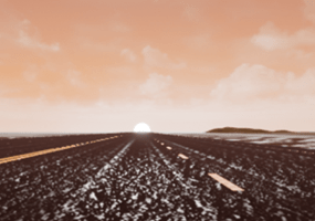
This table summarizes sun position settings for specific times of day.
| Time of Day | Settings | Unreal Editor Environment |
|---|---|---|
Midnight | Sun altitude: -90 Sun azimuth: 180 |
|
Sunrise in the north | Sun altitude: 0 Sun azimuth: 180 |
|
Noon | Sun altitude: 90 Sun azimuth: 180 |
|
This table summarizes settings for specific cloud conditions.
| Cloud Condition | Settings | Unreal Editor Environment |
|---|---|---|
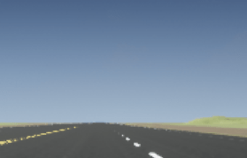
Clear | Cloud opacity: 0 |
|
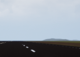
Heavy | Cloud opacity: 85 |
|
| Heavy | Enable Volumetric clouds: Selected Cloud Coverage: 50 Cloud layer altitude: 6 |
|


This table summarizes settings for specific fog conditions.
| Fog Condition | Settings | Unreal Editor Environment |
|---|---|---|
None | Fog density: 0 |
|
Heavy | Fog density: 100 |
|
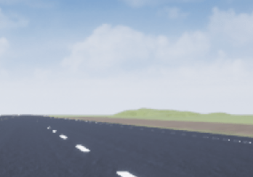
This table summarizes settings for specific rain conditions.
| Rain Condition | Settings | Unreal Editor Environment |
|---|---|---|
Light | Cloud opacity: 10 Rain density: 25 |
|
Heavy | Cloud opacity: 10 Rain density: 80 |
|


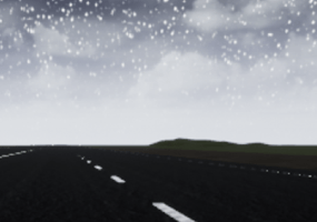
This table summarizes settings for specific snow conditions.
| Snow Condition | Settings | Unreal Editor Environment |
|---|---|---|
| Heavy | Snow density: 50 |
|

Sun
Azimuth angle in the horizontal plane measured from the south to the horizontal projection of the sun rays, in deg.
Use the Sun altitude and Sun azimuth parameters to control the time of day in the scene. For example, to specify sunrise in the north, set Sun altitude to 0 deg and Sun azimuth to 180 deg.
Dependencies
To enable this parameter, select Override scene weather.
Altitude angle in a vertical plane between the sun's rays and the horizontal projection of the rays, in deg.
Use the Sun altitude and Sun azimuth parameters to control the time of day in the scene. For example, to specify sunrise in the north, set Sun altitude to 0 deg and Sun azimuth to 180 deg.
Dependencies
To enable this parameter, select Override scene weather.
Select this check box to enable geospatial sun. Enabling geospatial sun is useful to simulate conditions near the poles or at locations with disproportionate lengths of day versus night.
In the 3D environment using the world coordinate system, the negative Y direction corresponds to east, the positive Y direction to west, the negative X direction to north, and the positive X direction to south.
Dependencies
To enable this parameter, select Override scene weather.
Latitude of geolocation on earth, specified as a scalar, in deg.
Dependencies
To enable this parameter, select Override scene weather and Enable geospatial sun.
Longitude of geolocation on earth, specified as a scalar, in deg.
Dependencies
To enable this parameter, select Override scene weather and Enable geospatial sun.
Date, specified as an integer in the format YYYY-MM-DD.
Dependencies
To enable this parameter, select Override scene weather and Enable geospatial sun.
Time, specified as an integer in the format HH:MM:SS.
Dependencies
To enable this parameter, select Override scene weather and Enable geospatial sun.
Time zone specifies the number of hours offset from the Coordinated Universal Time (UTC) or Greenwich Mean Time (GMT).
Dependencies
To enable this parameter, select Override scene weather and Enable geospatial sun.
Select this check box to enable daylight saving time.
Dependencies
To enable this parameter, select Override scene weather and Enable geospatial sun.
Cloud
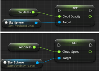
Parameter that corresponds to the Unreal Editor Cloud Speed global actor target value. The clouds move from west to east for positive values and east to west for negative values.
Use the Cloud opacity and Cloud speed parameters to control clouds in the scene.
Dependencies
To enable this parameter, select Override scene weather.
Parameter that corresponds to the Unreal Editor Cloud Opacity global actor target value, in percent. Zero is a cloudless scene.
Use the Cloud opacity and Cloud speed parameters to control clouds in the scene.
Dependencies
To enable this parameter, select Override scene weather.
Select this check box to enable volumetric clouds.
Dependencies
To enable this parameter, select Override scene weather.
Parameter that corresponds to the Unreal Editor Cloud Density global actor target value, in percent.
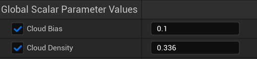
Use the Cloud coverage parameter to control clouds in the scene.
Dependencies
To enable this parameter, select Override scene weather and Enable volumetric clouds.
Parameter that corresponds to the Unreal Editor Layer Bottom Altitude global actor target value, in km.

Dependencies
To enable this parameter, select Override scene weather and Enable volumetric clouds.
Fog
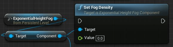
Parameter that corresponds to the Unreal Editor Set Fog Density and Set Start Distance target values, in percent.
Dependencies
To enable this parameter, select Override scene weather.
Rain
Parameter corresponding to the Unreal Editor local actor that controls rain density, wetness, rain puddles, and ripples, in percent.

Use the Cloud opacity and Rain density parameters to control rain in the scene.
Dependencies
To enable this parameter, select Override scene weather.
Select this check box to enable raindrops on the camera lens.

Dependencies
To enable this parameter, select Override scene weather.
Snow
This parameter corresponds to the Unreal Editor global actor that controls snow density, in percent.

Dependencies
To enable this parameter, select Override scene weather.
Geospatial
Select this check box to enable geospatial parameters and a variant subsystem.
ID of stored token, specified as a string. To create this token, create a Cesium Ion® account, then generate the token through this account. The Authentication Manager stores the token from Cesium Ion. For more information, see Visualize with Cesium and https://ion.cesium.com/.
Dependencies
To enable this parameter, select the Enable geospatial configuration check box.
Select this check box to position aerospace vehicles with respect to the Earth center. Use this option with the ECEF coordinate frame selection in the pack blocks.
Height at georeference point on the globe, specified as a real scalar. This parameter represents the height above the 1984 World Geodetic System (WGS84) ellipsoid model of the Earth at the latitude and longitude specified in Origin latitude and Origin longitude.
Dependencies
To enable this parameter:
Select the Enable geospatial configuration check box.
Clear the Use Earth center as origin (ECEF) check box.
Latitude, specified as a real scalar in decimal degrees.
Dependencies
To enable this parameter:
Select the Enable geospatial configuration check box.
Clear the Use Earth center as origin (ECEF) check box.
Longitude, specified as a real scalar in decimal degrees.
Dependencies
To enable this parameter:
Select the Enable geospatial configuration check box.
Clear the Use Earth center as origin (ECEF) check box.
Raster overlay type, specified as Aerial,
Aerial with labels, or
Road.
Dependencies
To enable this parameter, select the Enable geospatial configuration check box.
Local dataset IDs, specified as an array or vector.
Dependencies
To enable this parameter, select the Enable geospatial configuration check box.
Select this check box to add a georeferenced, location-accurate Sun Sky actor in simulation.
Dependencies
To enable this parameter, select the Enable geospatial configuration check box.
Current solar time, specified as scalar hours from midnight.
Dependencies
To enable this parameter:
Select the Enable geospatial configuration check box.
Select the Use advanced Sun sky check box.
Time zone, specified as hours offset from Greenwich Mean Time (GMT). To specify
hours before GMT, use a minus sign (-).
Dependencies
To enable this parameter:
Select the Enable geospatial configuration check box.
Select the Use advanced Sun sky check box.
Day, specified as a scalar from 1 to
31.
Dependencies
To enable this parameter:
Select the Enable geospatial configuration check box.
Select the Use advanced Sun sky check box.
Month, specified as a scalar from 1 to
12.
Dependencies
To enable this parameter:
Select the Enable geospatial configuration check box.
Select the Use advanced Sun sky check box.
Year, specified as a scalar real.
Select this check box to enable daylight saving time.
Dependencies
To enable this parameter:
Select the Enable geospatial configuration check box.
Select the Use advanced Sun sky check box.
Start day of daylight saving time, specified as a scalar from 1
to 31.
Dependencies
To enable this parameter:
Select the Enable geospatial configuration check box.
Select the Use advanced Sun sky check box.
Start month of daylight saving time, specified as a scalar from
1 to 12.
Dependencies
To enable this parameter:
Select the Enable geospatial configuration check box.
Select the Use advanced Sun sky check box.
Last day of daylight saving time, specified as a scalar from 1
to 31.
Dependencies
To enable this parameter:
Select the Enable geospatial configuration check box.
Select the Use advanced Sun sky check box.
Last month of daylight saving time, specified as a scalar from
1 to 12.
Dependencies
To enable this parameter:
Select the Enable geospatial configuration check box.
Select the Use advanced Sun sky check box.
Hour when daylight saving time switches, specified as a scalar from
1 to 24.
Dependencies
To enable this parameter:
Select the Enable geospatial configuration check box.
Select the Use advanced Sun sky check box.
Click to manage access tokens, such as create, update, and delete tokens.
Dependencies
To enable this parameter, select the Enable geospatial configuration check box.
Tileset source, specified as one of 'Earth Terrain', 'Moon Terrain',
'URL', or 'None'.
Dependencies
To enable this parameter, select the Enable geospatial configuration check box.
Data Types: string
File path of locally stored 3d tileset data, specified as a string.
Dependencies
To enable this parameter, select the Enable geospatial
configuration check box and set the
TilesetSource parameter to URL.
Data Types: string
More About
To control the scene weather and sun position, on the Weather tab, select Override scene weather. Use the enabled parameters to change the sun position, clouds, fog, and rain during the simulation.
Use Sun altitude and Sun azimuth to control the sun position.
Sun altitude — Altitude angle in a vertical plane between the sun rays and the horizontal projection of the rays.
Sun azimuth — Azimuth angle in the horizontal plane measured from the south to the horizontal projection of the sun rays.
Alternatively, select Enable geospatial sun to use Latitude, Longitude, Date, Time, and Time zone to control sun position. Enabling geospatial sun is useful to simulate conditions near the poles or at locations with disproportionate lengths of day versus night.
This table summarizes sun position settings for specific times of day.
| Time of Day | Settings | Unreal Editor Environment |
|---|---|---|
Midnight | Sun altitude: -90 Sun azimuth: 180 |
|
Sunrise in the north | Sun altitude: 0 Sun azimuth: 180 |
|
Noon | Sun altitude: 90 Sun azimuth: 180 |
|
Use Cloud opacity and Cloud speed to control clouds in the scene.
Cloud opacity — Unreal Editor Cloud Opacity global actor target value. Zero is a cloudless scene.
Cloud speed — Unreal Editor Cloud Speed global actor target value. The clouds move from west to east for positive values and east to west for negative values.
Select Enable volumetric clouds to use Cloud coverage and Cloud layer altitude to control volumetric clouds in the scene.
Cloud coverage — Unreal Editor Cloud Density global actor target value.
Cloud layer altitude — Unreal Editor Layer Bottom Altitude global actor target value.
This table summarizes settings for specific cloud conditions.
| Cloud Condition | Settings | Unreal Editor Environment |
|---|---|---|
Clear | Cloud opacity: 0 |
|
Heavy | Cloud opacity: 85 |
|
| Heavy | Enable Volumetric clouds: Selected Cloud Coverage: 50 Cloud layer altitude: 6 |
|
Use Fog density to control fog in the scene. Fog density corresponds to the Unreal Editor Set Fog Density.
This table summarizes settings for specific fog conditions.
| Fog Condition | Settings | Unreal Editor Environment |
|---|---|---|
None | Fog density: 0 |
|
Heavy | Fog density: 100 |
|
Use Cloud opacity and Rain density to control rain in the scene.
Cloud opacity — Unreal Editor Cloud Opacity global actor target value.
Rain density — Unreal Editor local actor that controls rain density, wetness, rain puddles, and ripples.
This table summarizes settings for specific rain conditions.
| Rain Condition | Settings | Unreal Editor Environment |
|---|---|---|
Light | Cloud opacity: 10 Rain density: 25 |
|
Heavy | Cloud opacity: 10 Rain density: 80 |
|
Use Snow density to control snow in the scene.
Snow density — Unreal Editor global actor that controls snow density.
This table summarizes settings for specific snow conditions.
| Snow Condition | Settings | Unreal Editor Environment |
|---|---|---|
| Heavy | Snow density: 50 |
|