NR TDD Symbol Based Scheduling Performance Evaluation
This example models a symbol-based scheduling scheme in time division duplexing (TDD) mode and evaluates the network performance. Symbol-based scheduling of resources allows shorter transmission durations spanning a few symbols in the slot. In TDD mode, physical uplink shared channel (PUSCH) and physical downlink shared channel (PDSCH) transmissions are scheduled in the same frequency band with separation in time domain. You can customize the scheduling strategy and evaluate network performance. The performance of the scheduling strategy is evaluated in terms of achieved throughput and fairness in resource sharing.
Introduction
The example considers the following operations within the gNB and UEs that facilitate UL and DL transmissions and receptions.

The complete PUSCH or PDSCH packet is transmitted in the first symbol of its allocated symbol set. Receiver processes the packet in the symbol just after the last symbol in the allocated symbol set.
This example models:
Configurable TDD DL-UL pattern.
Slot-based and symbol-based DL and UL scheduling. UL scheduler ensures that the UEs get the required PUSCH preparation time.
Noncontiguous allocation of frequency domain resources in terms of resource block groups (RBGs).
Configurable subcarrier spacing resulting in different slot durations.
Configurable demodulation reference signal (DM-RS) properties.
Asynchronous hybrid automatic repeat request (HARQ) mechanism.
Periodic DL and UL application traffic pattern.
RLC operating in UM mode.
Single bandwidth part covering the entire carrier bandwidth.
Following control packets are assumed to be sent out of band i.e. without the need of resources for transmission and assured error-free reception: UL assignment, DL assignment, buffer status report (BSR), PDSCH feedback, and CQI report. These control packets follow the TDD DL and UL timings. For example, BSR and PDSCH feedback are sent in UL time while resource assignments are sent in DL time.
TDD DL-UL Pattern Configuration
NR provides a flexible way of configuring the DL and UL resources. The parameters used to define a custom TDD configuration are:
DL-UL transmission periodicity in ms.
Reference subcarrier spacing to calculate the number of slots in the DL-UL pattern. In this example, it is assumed to be same as actual subcarrier spacing used for transmission.
Number of consecutive full DL slots at the beginning of each DL-UL pattern.
Number of consecutive DL symbols in the beginning of the slot following the last full DL slot.
Number of consecutive full UL slots at the end of each DL-UL pattern.
Number of consecutive UL symbols in the end of the slot preceding the first full UL slot.
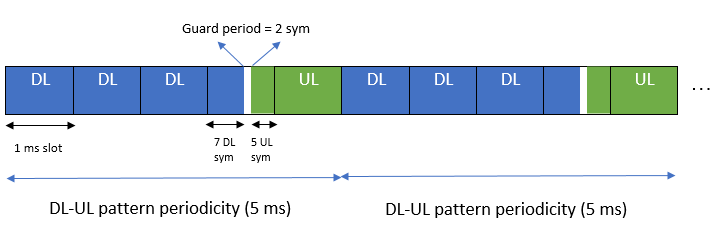
The example does not model flexible symbols, so the symbols with unspecified symbol type are assumed for guard period. Here is an example of resulting TDD DL-UL pattern based on these parameters. This DL-UL pattern repeats itself in the timeline.
reference_scs= 15 kHz (i.e. 1 ms slot),DLULPeriodicity= 5 ms,numDLSlots= 3,numDLSyms= 7,numULSlots= 1,numULSyms= 5
Number of slots in DL-UL periodicity with respect to reference SCS of 15 kHz, NumSlotsDLULPeriodicity = 5
NumberOfGuardSymbols = TotalSymbolsInPattern - TotalSymbolsWithTypeSpecified
= (14 * NumSlotsDLULPeriodicity) - (numDLSlots*14 + numDLSyms + numULSyms + numULSlots*14)
= 2 symbols
Scheduler
UL and DL schedulers distribute the UL and DL resources respectively among the UEs. You can choose any one of the implemented scheduling strategies: proportional fair (PF), best CQI, or round-robin (RR). The various supported inputs to the schedulers are shown along with the scheduling strategies that consider them.
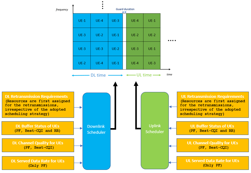
Both UL and DL schedulers run at the start of a slot when the first symbol is a DL symbol. Schedulers run in DL time so that assignments (UL and DL) can be instantly sent to UEs in the DL direction. The run time of the scheduler algorithm as well as the propagation delay is assumed to be zero. The output of scheduling operations is an array of assignments. Each assignment contains the information fields to fully define a PUSCH or PDSCH transmission.
UL Scheduler
The UL scheduling operation follows these two steps.
Select slots to be scheduled: The criteria used in this example selects all the upcoming slots (including the current one) containing unscheduled UL symbols that must be scheduled now. Such slots must be scheduled now as they cannot be scheduled in the next slot with DL symbols, depending on the value of PUSCH preparation time capability of the UEs. It ensures that the UL resources are scheduled as close as possible to the actual transmission time.
Below are 2 examples to explain how UL slots are selected in this example for scheduling, based on PUSCH preparation time.
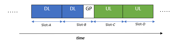
(i) Assuming that the UEs require PUSCH preparation time equivalent to 10 symbols, when the UL scheduler runs in Slot-A, it does not select any slot for scheduling. Because scheduling in the next slot (i.e. Slot-B) provides enough PUSCH preparation time (14 symbols) for the UL transmission in Slot-C. Later, when the UL scheduler runs in Slot-B, it selects both Slot-C and Slot-D for scheduling. Slot-D is scheduled in Slot-B itself (and not in Slot-C) because Slot-C is a full UL slot and hence does not have any DL symbols for sending the assignments in the DL direction.
(ii) Assuming that the UEs require PUSCH preparation time equivalent to 16 symbols, Slot-C is scheduled in Slot-A itself. Because scheduling in Slot-B would only provide 14 symbols of PUSCH preparation time to start transmission in Slot-C. Slot-D is scheduled in Slot-B.
2. Resource scheduling: If any slots are selected in the first step, assign the UL resources of those slots to the UEs.
DL scheduler
The DL scheduler runs at each slot beginning with a DL symbol and assign resources of the first upcoming slot containing DL symbols. So, when the DL scheduler runs at the start of Slot-A, it schedules DL resources of Slot-B.
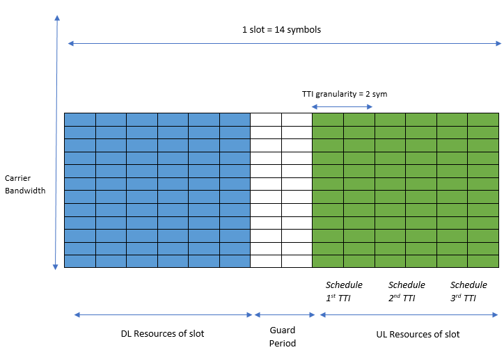
Symbol based scheduling
NR allows the TTI to start at any symbol position in the slot and with TTI granularity in symbols. The figure shows the way UL scheduler operates in this example to schedule UL symbols of a slot with TTI granularity of two symbols. The slot shown contains six UL symbols. Scheduler completes the iteration of the UL symbols in three iterations with each iteration distributing the frequency resources of two symbols. The DL scheduler also follows a similar approach for DL scheduling.
Scenario Configuration
Check if the Communications Toolbox Wireless Network Simulation Library support package is installed. If the support package is not installed, MATLAB® returns an error with a link to download and install the support package.
wirelessnetworkSupportPackageCheck
Configure simulation parameters in the simParameters structure.
rng('default'); % Reset the random number generator
simParameters = []; % Clear simParameters variable
simParameters.NumFramesSim = 100; % Simulation time in terms of number of 10 ms frames
simParameters.SchedulingType = 1; % Set the value to 0 (slot-based scheduling) or 1 (symbol-based scheduling)
Specify the number of UEs in the cell, assuming that UEs have sequential radio network temporary identifiers (RNTIs) from 1 to simParameters.NumUEs. If you change the number of UEs, ensure that the number of rows in simParameters.UEPosition parameter equals to the value of simParameters.NumUEs.
simParameters.NumUEs = 4;
% Assign position to the UEs assuming that the gNB is at (0, 0, 0). N-by-3
% matrix where 'N' is the number of UEs. Each row has (x, y, z) position of a
% UE (in meters)
simParameters.UEPosition = [100 0 0;
                            150 0 0;
                            300 0 0;
                            400 0 0];
% Validate the UE positions
validateattributes(simParameters.UEPosition,{'numeric'},{'nonempty','real','nrows',simParameters.NumUEs,'ncols',3, ...
    'finite'},'simParameters.UEPosition','UEPosition');
Set the channel bandwidth to 5 MHz and the subcarrier spacing (SCS) to 15 kHz as defined in 3GPP TS 38.104 Section 5.3.2. The complete bandwidth is assumed to be allotted for PUSCH or PDSCH.
simParameters.NumRBs = 25;
simParameters.SCS = 15; % kHz
simParameters.DLBandwidth = 5e6; % Hz
simParameters.ULBandwidth = 5e6; % Hz
simParameters.DLCarrierFreq = 2.595e9; % Hz
simParameters.ULCarrierFreq = 2.595e9; % Hz
Specify the TDD DL-UL pattern. The reference subcarrier spacing used for calculating slot duration for the pattern is assumed to be same as actual subcarrier spacing used for transmission as defined by simParameters.SCS. Keep only the symbols intended for guard period during DLULPeriodicity with type (DL or UL) unspecified.
simParameters.DLULPeriodicity = 5; % Duration of the DL-UL pattern in ms
simParameters.NumDLSlots = 2; % Number of consecutive full DL slots at the beginning of each DL-UL pattern
simParameters.NumDLSyms = 8; % Number of consecutive DL symbols in the beginning of the slot following the last full DL slot
simParameters.NumULSyms = 4; % Number of consecutive UL symbols in the end of the slot preceding the first full UL slot
simParameters.NumULSlots = 2; % Number of consecutive full UL slots at the end of each DL-UL pattern
Specify the scheduling strategy, the time domain resource assignment granualarity and the maximum limit on the RBs allotted for PDSCH and PUSCH. The time domain resource assignment granualarity is applicable only for symbol-based scheduling. If the number of symbols (DL or UL) are less than the configured time domain resource assignment granularity, then a smaller valid granularity is chosen. For slot-based scheduling, biggest possible granularity in a slot is chosen. The RB transmission limit applies only to new transmissions and not to the retransmissions.
simParameters.SchedulerStrategy = 'PF'; % Supported scheduling strategies: 'PF', 'RR' and 'BestCQI'
simParameters.TTIGranularity = 4;
simParameters.RBAllocationLimitUL = 15; % For PUSCH
simParameters.RBAllocationLimitDL = 15; % For PDSCH
Set the UL scheduling related configurations - BSR periodicity and PUSCH preparation time. gNB ensures that PUSCH assignment is received at the UEs at least PUSCHPrepTime ahead of the transmission time.
simParameters.BSRPeriodicity = 1; % Buffer status report transmission periodicity (in ms)
simParameters.PUSCHPrepTime = 200; % In microseconds
Set the channel quality related configurations for the UEs. Channel quality is periodically improved or deteriorated by CQI Delta for all RBs of a UE. Whether channel conditions for a particular UE improve or deteriorate is randomly determined by: RB_CQI = RB_CQI +/- CQIDelta. However, the maximum allowed CQI value depends on the UE position and is determined by CQIvsDistance mapping table. This mapping is only applicable when passthrough PHY is used.
simParameters.ChannelUpdatePeriodicity = 0.2; % In sec
simParameters.CQIDelta = 1;
% Mapping between distance from gNB (first column in meters) and maximum achievable UL CQI value (second column)
simParameters.CQIvsDistance = [
    200  15;
    300  12;
    500  10;
    1000  8;
    1200  7];
Specify the PUSCH and PDSCH associated DMRS configurations.
simParameters.DMRSTypeAPosition = 2; % Type-A DM-RS position as 2 or 3
% PUSCH DM-RS configuration
simParameters.PUSCHDMRSAdditionalPosTypeB = 0;
simParameters.PUSCHDMRSAdditionalPosTypeA = 0;
simParameters.PUSCHDMRSConfigurationType = 1;
% PDSCH DM-RS configuration
simParameters.PDSCHDMRSAdditionalPosTypeB = 0;
simParameters.PDSCHDMRSAdditionalPosTypeA = 0;
simParameters.PDSCHDMRSConfigurationType = 1;
Application traffic configuration
Set the periodic DL and UL application traffic pattern for UEs.
% Set the periodic DL and UL application traffic pattern for UEs
dlAppDataRate = 16e4*ones(simParameters.NumUEs,1); % DL application data rate in kilo bits per second (kbps)
ulAppDataRate = 16e4*ones(simParameters.NumUEs,1); % UL application data rate in kbps
% Validate the DL application data rate
validateattributes(dlAppDataRate, {'numeric'},{'nonempty','vector','numel',simParameters.NumUEs,'finite','>',0}, ...
    'dlAppDataRate','dlAppDataRate');
% Validate the UL application data rate
validateattributes(ulAppDataRate,{'numeric'},{'nonempty','vector','numel',simParameters.NumUEs,'finite','>',0}, ...
    'ulAppDataRate', 'ulAppDataRate');
Logging and visualization configuration
The CQIVisualization and RBVisualization parameters control the display of the CQI visualization and the RB assignment visualization respectively. To enable the RB visualization plot, set the RBVisualization field to true.
simParameters.CQIVisualization = false;
simParameters.RBVisualization = false;
Set the enableTraces as true to log the traces. If the enableTraces is set to false, then CQIVisualization and RBVisualization are disabled automatically and traces are not logged in the simulation. To speed up the simulation, set the enableTraces to false.
enableTraces = true;
The example updates the metrics plots periodically. Set the number of updates during the simulation. Number of steps must be less than or equal to number of slots in simulation
simParameters.NumMetricsSteps = 20;
Write the logs to MAT-files. The example uses these logs for post-simulation analysis and visualization.
parametersLogFile = 'simParameters'; % For logging the simulation parameters
simulationLogFile = 'simulationLogs'; % For logging the simulation traces
simulationMetricsFile = 'simulationMetrics'; % For logging the simulation metrics
Derived Parameters
Compute the derived parameters based on the primary configuration parameters specified in the previous section and additionally set some example-specific constants.
simParameters.DuplexMode = 1; % FDD (Value as 0) or TDD (Value as 1)
simParameters.NCellID = 1; % Physical cell ID
simParameters.Position = [0 0 0]; % Position of gNB in (x,y,z) coordinates
Compute the number of slots in the simulation.
numSlotsSim = (simParameters.NumFramesSim * 10 * simParameters.SCS)/15;
Determine the PDSCH/PUSCH mapping type.
if simParameters.SchedulingType % Symbol-based scheduling
    simParameters.PUSCHMappingType = 'B';
    simParameters.PDSCHMappingType = 'B';
else % Slot-based scheduling
    simParameters.PUSCHMappingType = 'A';
    simParameters.PDSCHMappingType = 'A';
end
Set the interval at which the example updates metrics visualization in terms of number of slots.
simParameters.MetricsStepSize = ceil(numSlotsSim / simParameters.NumMetricsSteps);
Specify one logical channel for each UE, and set the logical channel configuration for all nodes (UEs and gNBs) in the example.
numLogicalChannels = 1;
simParameters.LCHConfig.LCID = 4;
Specify the RLC entity type in the range [0, 3]. The values 0, 1, 2, and 3 indicate RLC UM unidirectional DL entity, RLC UM unidirectional UL entity, RLC UM bidirectional entity, and RLC AM entity, respectively.
simParameters.RLCConfig.EntityType = 2;
Construct information for RLC logger.
lchInfo = repmat(struct('RNTI',[],'LCID',[],'EntityDir',[]), [simParameters.NumUEs 1]);
for idx = 1:simParameters.NumUEs
    lchInfo(idx).RNTI = idx;
    lchInfo(idx).LCID = simParameters.LCHConfig.LCID;
    lchInfo(idx).EntityDir = simParameters.RLCConfig.EntityType;
end
Create RLC channel configuration structure.
rlcChannelConfigStruct.LCGID = 1; % Mapping between logical channel and logical channel group ID
rlcChannelConfigStruct.Priority = 1; % Priority of each logical channel
rlcChannelConfigStruct.PBR = 8; % Prioritized bitrate (PBR), in kilobytes per second, of each logical channel
rlcChannelConfigStruct.BSD = 10; % Bucket size duration (BSD), in ms, of each logical channel
rlcChannelConfigStruct.EntityType = simParameters.RLCConfig.EntityType;
rlcChannelConfigStruct.LogicalChannelID = simParameters.LCHConfig.LCID;
Set the maximum RLC SDU length (in bytes) as per 3GPP TS 38.323
simParameters.maxRLCSDULength = 9000;
Calculate maximum achievable CQI value for the UEs based on their distance from the gNB
maxUECQIs = zeros(simParameters.NumUEs, 1); % To store the maximum achievable CQI value for UEs
for ueIdx = 1:simParameters.NumUEs
    % Based on the distance of the UE from gNB, find matching row in CQIvsDistance mapping
    matchingRowIdx = find(simParameters.CQIvsDistance(:, 1) > simParameters.UEPosition(ueIdx,1));
    if isempty(matchingRowIdx)
        maxUECQIs(ueIdx) = simParameters.CQIvsDistance(end, 2);
    else
        maxUECQIs(ueIdx) = simParameters.CQIvsDistance(matchingRowIdx(1), 2);
    end
end
Define initial UL and DL channel quality as an N-by-P matrix, where 'N' is the number of UEs and 'P' is the number of RBs in the carrier bandwidth. The initial value of CQI for each RB, for each UE, is given randomly and is limited by the maximum achievable CQI value corresponding to the distance of the UE from gNB.
simParameters.InitialChannelQualityUL = zeros(simParameters.NumUEs, simParameters.NumRBs); % To store current UL CQI values on the RBs for different UEs
simParameters.InitialChannelQualityDL = zeros(simParameters.NumUEs, simParameters.NumRBs); % To store current DL CQI values on the RBs for different UEs
for ueIdx = 1:simParameters.NumUEs
    % Assign random CQI values for the RBs, limited by the maximum achievable CQI value
    simParameters.InitialChannelQualityUL(ueIdx, :) = randi([1 maxUECQIs(ueIdx)], 1, simParameters.NumRBs);
    % Initially, DL and UL CQI values are assumed to be equal
    simParameters.InitialChannelQualityDL(ueIdx, :) = simParameters.InitialChannelQualityUL(ueIdx, :);
end
gNB and UEs Setup
Create the gNB and UE objects, initialize the channel quality information for UEs and set up the logical channel at gNB and UE. The helper classes hNRGNB.m and hNRUE.m create gNB and UE node respectively, containing the RLC and MAC layer. For MAC layer, hNRGNB.m uses the helper class hNRGNBMAC.m to implement the gNB MAC functionality and hNRUE.m uses hNRUEMAC.m to implement the UE MAC functionality. Schedulers are implemented in hNRSchedulerRoundRobin.m (RR), hNRSchedulerProportionalFair.m (PF), hNRSchedulerBestCQI.m (Best CQI). All the schedulers inherit from the base class hNRScheduler.m which contains the core scheduling functionality. For RLC layer, both hNRGNB.m and hNRUE.m use hNRUMEntity.m to implement the functionality of the RLC transmitter and receiver. Passthrough PHY layer for UE and gNB is implemented in hNRUEPassThroughPhy.m and hNRGNBPassThroughPhy.m, respectively.
Create the gNB node and add scheduler
gNB = hNRGNB(simParameters);
switch(simParameters.SchedulerStrategy)
    case 'RR' % Round-robin scheduler
        scheduler = hNRSchedulerRoundRobin(simParameters);
    case 'PF' % Proportional fair scheduler
        scheduler = hNRSchedulerProportionalFair(simParameters);
    case 'BestCQI' % Best CQI scheduler
        scheduler = hNRSchedulerBestCQI(simParameters);
end
addScheduler(gNB, scheduler); % Add scheduler to gNB

gNB.PhyEntity = hNRGNBPassThroughPhy(simParameters); % Add passthrough PHY
configurePhy(gNB, simParameters);
setPhyInterface(gNB); % Set the interface to PHY layer
Create the set of UE nodes.
UEs = cell(simParameters.NumUEs, 1);
for ueIdx = 1:simParameters.NumUEs
    simParameters.Position = simParameters.UEPosition(ueIdx, :); % Position of the UE
    UEs{ueIdx} = hNRUE(simParameters, ueIdx);
    UEs{ueIdx}.PhyEntity = hNRUEPassThroughPhy(simParameters, ueIdx); % Add passthrough PHY
    configurePhy(UEs{ueIdx}, simParameters);
    setPhyInterface(UEs{ueIdx}); % Set the interface to PHY layer

    % Initialize the UL CQI values at gNB scheduler
    channelQualityInfoUL = struct('RNTI', ueIdx, 'CQI', simParameters.InitialChannelQualityUL(ueIdx, :));
    updateChannelQualityUL(gNB.MACEntity.Scheduler, channelQualityInfoUL);

    % Initialize the DL CQI values at gNB scheduler
    channelQualityInfoDL = struct('RNTI', ueIdx, 'CQI', simParameters.InitialChannelQualityDL(ueIdx, :));
    updateChannelQualityDL(gNB.MACEntity.Scheduler, channelQualityInfoDL);

    % Initialize the DL CQI values at UE for packet error probability estimation
    updateChannelQualityDL(UEs{ueIdx}.MACEntity, channelQualityInfoDL);

    % Setup logical channel at gNB for the UE
    configureLogicalChannel(gNB, ueIdx, rlcChannelConfigStruct);
    % Setup logical channel at UE
    configureLogicalChannel(UEs{ueIdx}, ueIdx, rlcChannelConfigStruct);

    % Create an object for On-Off network traffic pattern and add it to the
    % specified UE. This object generates the uplink (UL) data traffic on the UE
    ulApp = networkTrafficOnOff('GeneratePacket', true, ...
        'OnTime', simParameters.NumFramesSim/100, 'OffTime', 0, 'DataRate', ulAppDataRate(ueIdx));
    UEs{ueIdx}.addApplication(ueIdx, simParameters.LCHConfig.LCID, ulApp);

    % Create an object for On-Off network traffic pattern for the specified
    % UE and add it to the gNB. This object generates the downlink (DL) data
    % traffic on the gNB for the UE
    dlApp = networkTrafficOnOff('GeneratePacket', true, ...
        'OnTime', simParameters.NumFramesSim/100, 'OffTime', 0, 'DataRate', dlAppDataRate(ueIdx));
    gNB.addApplication(ueIdx, simParameters.LCHConfig.LCID, dlApp);
end
Simulation
% Initialize wireless network simulator
nrNodes = [{gNB}; UEs];
networkSimulator = hWirelessNetworkSimulator(nrNodes);
Create objects to log RLC and MAC traces.
if enableTraces

    % RLC metrics are logged for every 1 slot duration
    simRLCLogger = hNRRLCLogger(simParameters, lchInfo, networkSimulator, gNB, UEs);

    simSchedulingLogger = hNRSchedulingLogger(simParameters, networkSimulator, gNB, UEs);

    % Create an object for CQI and RB grid visualization
    if simParameters.CQIVisualization || simParameters.RBVisualization
        gridVisualizer = hNRGridVisualizer(simParameters, 'MACLogger', simSchedulingLogger);
    end
end
Create an object for RLC and MAC metrics visualization.
metricsVisualizer = hNRMetricsVisualizer(simParameters, 'EnableSchedulerMetricsPlots', true, ...
    'EnableRLCMetricsPlots', true, 'LCHInfo', lchInfo, 'NetworkSimulator', networkSimulator, 'GNB', gNB, 'UEs', UEs);
Run the simulation for the specified NumFramesSim frames.
% Calculate the simulation duration (in seconds) from 'NumFramesSim'
simulationTime = simParameters.NumFramesSim * 1e-2;
% Run the simulation
run(networkSimulator, simulationTime);

At the end of the simulation, the achieved value for system performance indicator is compared to their theoretical peak values (considering zero overheads). Performance indicators displayed are achieved data rate (UL and DL), and achieved spectral efficiency (UL and DL). The peak values are calculated as per 3GPP TR 37.910.
displayPerformanceIndicators(metricsVisualizer);
Peak UL Throughput: 14.22 Mbps. Achieved Cell UL Throughput: 5.72 Mbps
Achieved UL Throughput for each UE: [2.13        1.83           1        0.75]
Achieved Cell UL Goodput: 5.18 Mbps
Achieved UL Goodput for each UE: [1.94        1.67         0.9        0.67]
Peak UL spectral efficiency: 2.84 bits/s/Hz. Achieved UL spectral efficiency for cell: 1.04 bits/s/Hz

Peak DL Throughput: 16.00 Mbps. Achieved Cell DL Throughput: 5.35 Mbps
Achieved DL Throughput for each UE: [1.99        1.73        0.92        0.72]
Achieved Cell DL Goodput: 4.82 Mbps
Achieved DL Goodput for each UE: [1.78        1.56        0.82        0.64]
Peak DL spectral efficiency: 3.20 bits/s/Hz. Achieved DL spectral efficiency for cell: 0.96 bits/s/Hz
Get the simulation metrics and save it in a MAT-file. The simulation metrics are saved in a MAT-file with the file name as simulationMetricsFile
metrics = getMetrics(metricsVisualizer);
save(simulationMetricsFile, 'metrics'); % Save simulation metrics in a MAT-file
Simulation Visualization
The five types of runtime visualization shown are:
Display of CQI values for UEs over the channel bandwidth: For details, see the 'Channel Quality Visualization' figure.
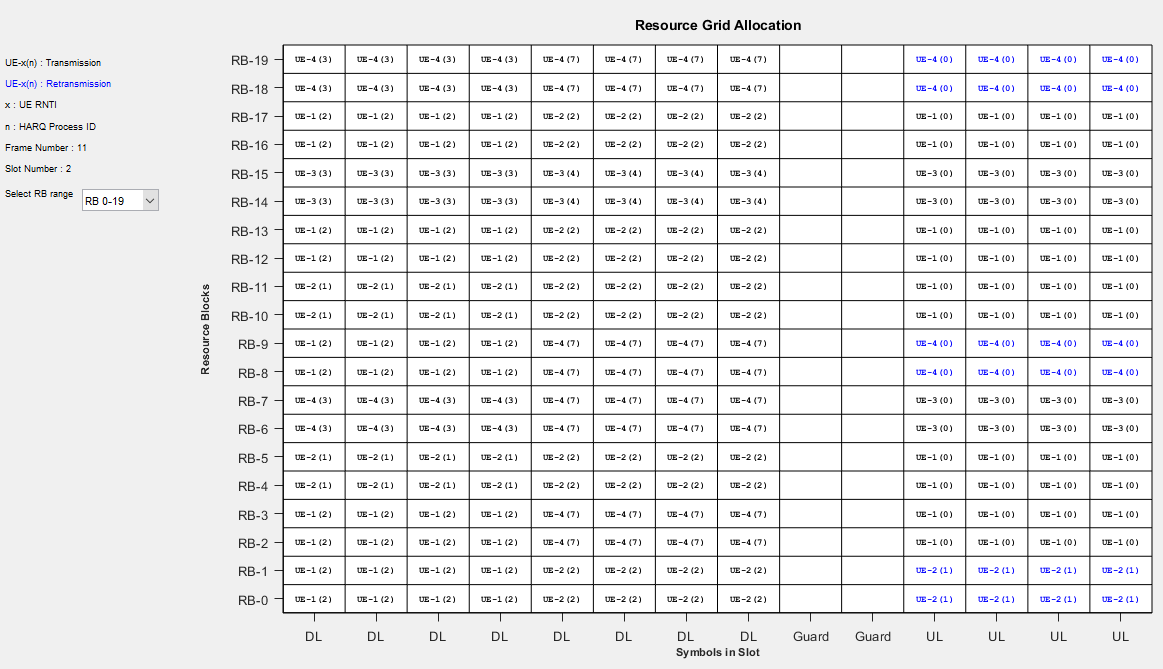
Display of resource grid assignment to UEs: The 2-D time-frequency grid shows the resource allocation to the UEs. For slot-based scheduling, it updates every 10 ms (frame length), and shows the RB allocation to the UEs in the previous frame. For symbol-based scheduling, it updates every slot, and shows the RB allocation of symbols of the previous slot. For details, see the 'Resource Grid Allocation' figure.
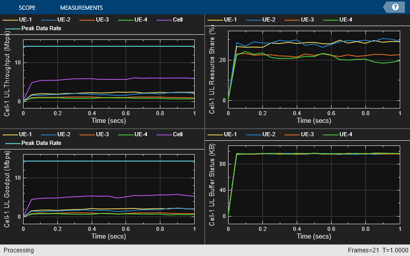
Display of UL scheduling metrics plots: The 'Uplink Scheduler Performance Metrics' figure includes plots of the: UL throughput (per UE and cell), UL goodput (per UE and cell), resource share percentage among UEs (out of the total UL resources) to convey the fairness of scheduling, and pending UL buffer status of the UEs to show whether UEs are getting sufficient resources. The maximum achievable data rate value for UL throughput is shown with a dashed line in throughput and goodput plots. The performance metrics plots update for every
metricsStepSizeslots. Here, throughput is the number of bytes transmitted (including retransmissions) by a UE during a specified period, and goodput is the number of newly transmitted bytes by a UE during a specified period.Display of DL scheduling metrics plots: Like uplink metrics plots, the 'Downlink Scheduler Performance Metrics' displays corresponding subplots for DL direction. The performance metrics plots update for every
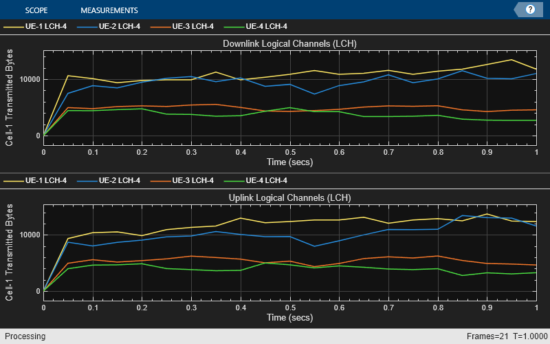
metricsStepSizeslots. Here, throughput is the number of bytes transmitted (including retransmissions) by a gNB during a specified period, and goodput is the number of newly transmitted bytes by a gNB during a specified period to each UE.Display of RLC metrics plot: The 'RLC Metrics Visualization' figure shows the number of bytes transmitted by RLC layer (per logical channel) for each UE. The RLC metrics plot updates for every
metricsStepSizeslots.
Simulation Logs
The parameters used for simulation and the simulation logs are saved in MAT-files for post-simulation analysis and visualization. The simulation parameters are saved in MAT-file with filename as the value of configuration parameter parametersLogFile. The per time step logs, scheduling assignment logs, and RLC logs are saved in the MAT-file simulationLogFile. After the simulation, open it to load TimeStepLogs, SchedulingAssignmentLogs, and RLCLogs in the workspace.
Time step logs: The table shows a sample time step entry. Each row of the table represents a symbol or a slot, based on the chosen scheduling type (symbol-based or slot-based). The information in a row is for DL, if the type of symbol (or slot) is DL. Likewise, for UL symbol (or slot).

Each row contains the following information:
Timestamp: Timestamp (in milliseconds)
Frame: Frame number.
Slot: Slot number in the frame.
Symbol: Symbol number in the slot (Only for symbol-based scheduling).Type: Symbol (or Slot) type as 'DL', 'UL', or 'Guard'. For slot-based scheduling, type can only be DL/UL. As the slot containing the guard symbols is assumed to be a DL slot with guard symbols at the end of the slot.RBG Allocation Bitmap: N-by-P bitmap matrix, where N is the number of UEs and P is the number of RBGs in the bandwidth. If an RBG is assigned to a particular UE, the corresponding bit is set to 1. For example, [ 0 0 1 1 0 1 0 1 0 1 0 0 0; 1 1 0 0 0 0 0 0 0 0 1 0 0; 0 0 0 0 1 0 1 0 1 0 0 1 1; 0 0 0 0 0 0 0 0 0 0 0 0 0] means, that the bandwidth has 13 RBGs and UE-1 is assigned the RBG indices 2, 3, 5, 7, and 9; UE-2 is assigned the RBG indices: 0, 1, and 10; UE-3 is assigned the RBG indices: 4, 6, 8, 11, and 12; and UE-4 is not assigned any RBG.
MCS: Row vector of length N where N is the number of UEs. Each value corresponds to the modulation and coding scheme (MCS) index for the PUSCH or PDSCH transmission. For example, [10 12 8 -1] means that only UE-1, UE-2, and UE-3 are assigned UL resources (symbol type is 'UL') for this symbol and use MCS values 10, 12, and 8, respectively.
HARQ Process: Row vector of length N, where N is the number of UEs. The value is the HARQ process ID used by UE for the PUSCH transmission or used by gNB for PDSCH transmission. For example, [0 3 6 -1] means that only UE-1, UE-2, and UE-3 are assigned UL resources (symbol type is 'UL') for this symbol and use the HARQ process IDs 0, 3, and 6, respectively.
NDI: Row vector of length N, where N is the number of UEs. The value is the NDI flag value in the assignment for PUSCH or PDSCH transmission. For example, [0 0 1 -1] means that only UE-1, UE-2, and UE-3 are assigned UL resources for this symbol and use the NDI flag values (which determine whether a new transmission or a retransmission is done) are 0, 0, and 1, respectively.
Tx Type: Tx Type specifies the transmission type (new transmission or retransmission). Row vector of length N, where N is the number of UEs. Possible values are either 'newTx', 'reTx', or 'noTx'. 'noTx' means that the UE is not allotted PUSCH or PDSCH resources. For example: ['newTx' 'newTx' 'reTx' 'noTx'] means that only UE-1, UE-2, and UE-3 are assigned UL resources for this symbol. UE-1 and UE-2 transmit a new packet from the specified HARQ process, while UE-3 retransmits the packet in the buffer of the specified HARQ process.
CQI for UEs: N-by-P matrix, where N is the number of UEs and P is the number of RBs in the bandwidth. A matrix element at position (i, j) corresponds to the CQI value for UE with RNTI i at RB j.
HARQ NDI Status: N-by-P matrix, where N is the number of UEs and P is the number of HARQ processes. A matrix element at position (i, j) is the last received NDI flag at UE i for DL or UL HARQ process ID j. For new transmissions, this value and the NDI flag in the PUSCH or PDSCH assignment must toggle for the HARQ process in the assignment.
Throughput Bytes: Row vector of length N, where N is the number of UEs. The values represent UL or DL MAC bytes transmitted by or for the UEs in this symbol. Note that the total throughput bytes for the complete PUSCH or PDSCH transmission are shown in the row corresponding to the first symbol of the transmission.
Goodput Bytes: Row vector of length N, where N is the number of UEs. The values represent new UL or DL transmission MAC bytes transmitted by or for the UEs in this symbol. Like throughput, all the goodput bytes for the complete PUSCH or PDSCH are shown in the row corresponding to first symbol of the transmission.
Buffer Status of UEs: Row vector of length N, where N is the number of UEs. The values represent the amount of UL direction pending buffers at UEs (or DL direction pending buffers for UEs at gNB).
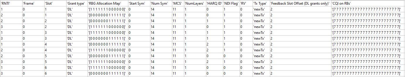
Scheduling assignment logs: Information of all the scheduling assignments and related information is logged in this table. Each row is one UL or DL assignment.
RLC logs: Each row in the RLC logs represents a slot and contains this information:
Timestamp: Timestamp (in milliseconds)
Frame: Frame number.
Slot: Slot number in the frame.
UE RLC statistics: N-by-P cell, where N is the product of the number of UEs and the number of logical channels, and P is the number of statistics collected. Each row represents statistics of a logical channel in a UE. The last row contains the cumulative RLC statistics of the entire simulation.
gNB RLC statistics: N-by-P cell, where N is the product of the number of UEs and the number of logical channels, and P is the number of statistics collected. Each row represents statistics of a logical channel of a UE at gNB. The last row contains the cumulative RLC statistics of the entire simulation.
Each row of the UE and gNB RLC statistics table represents a logical channel of a UE and contains:
RNTI: Radio network temporary identifier of a UE.
LCID: Logical channel identifier.
TxDataPDU: Number of data PDUs sent by RLC to MAC layer.
TxDataBytes: Number of data bytes sent by RLC to MAC layer.
ReTxDataPDU: Number of data PDUs retransmitted by RLC to MAC layer.
ReTxDataBytes: Number of data bytes retransmitted by RLC to MAC layer.
TxControlPDU: Number of control PDUs sent by RLC to MAC layer.
TxControlBytes: Number of control bytes sent by RLC to MAC layer.
TxPacketsDropped: Number of RLC SDUs dropped by RLC due to Tx buffer overflow.
TxBytesDropped: Number of bytes dropped by RLC due to Tx buffer overflow.
TimerPollRetransmitTimedOut: Number of times the poll retransmit timer expired.
RxDataPDU: Number of data PDUs received by RLC from MAC layer.
RxDataBytes: Number of data bytes received by RLC from MAC layer.
RxDataPDUDropped: Number of received data PDUs from MAC which are dropped by RLC layer.
RxDataBytesDropped: Number of received data bytes from MAC which are dropped by RLC layer.
RxDataPDUDuplicate: Number of duplicate PDUs received by RLC from MAC layer.
RxDataBytesDuplicate: Number of duplicate data bytes received by RLC from MAC layer.
RxControlPDU: Number of control PDUs received by RLC from MAC layer.
RxControlBytes: Number of control bytes received by RLC from MAC layer.
TimerReassemblyTimedOut: Number of times the reassembly timer expired.
TimerStatusProhibitTimedOut: Number of times the status prohibit timer expired.
You can run the script NRPostSimVisualization to get a post-simulation visualization of logs. In the post-simulation script, you are provided with variable isLogReplay, which provides these options to visualize 'Resource Grid Allocation' and 'Channel Quality Visualization' figures.
Set
isLogReplaytotruefor a replay of the simulation logs.Set
isLogReplaytofalseto analyze the details of a particular frame or a particular slot of a frame. In the 'Resource Grid Allocation' window, input the frame number and slot number to visualize the resource assignment of the particular slot, if scheduling type is symbol-based. For slot-based scheduling, enter the frame number to visualize the resource assignment for the entire frame. The frame number entered here controls the frame number for 'Channel Quality Visualization' figure too.
if enableTraces
    % Read the logs and write them to MAT-files
    % Get the logs
    simulationLogs = cell(1,1);
    logInfo = struct('TimeStepLogs',[], 'SchedulingAssignmentLogs',[] ,'RLCLogs', []);
    [logInfo.TimeStepLogs] = getSchedulingLogs(simSchedulingLogger);
    logInfo.SchedulingAssignmentLogs = getGrantLogs(simSchedulingLogger); % Scheduling assignments log
    logInfo.RLCLogs = getRLCLogs(simRLCLogger); % RLC statistics logs
    simulationLogs{1} = logInfo;

    save(simulationLogFile, 'simulationLogs'); % Save simulation logs in a MAT-file
    save(parametersLogFile, 'simParameters'); % Save simulation parameters in a MAT-file
end
Further Exploration
You can use this example to further explore these options.
Custom scheduling
You can modify the existing scheduling strategy to implement a custom one. Use Custom Scheduler in 5G System-Level Simulation example explains how to create a custom scheduling strategy and plug it into system-level simulation.
Use 5G Toolbox™ physical layer
You can also switch from passthrough PHY layer to 5G Toolbox™ physical layer processing by creating PHY objects using hNRGNBPhy.m and hNRUEPhy.m.
Use RLC AM
You can also switch the operating mode of an RLC entity from UM to acknowledged mode (AM) by modifying the input structure fields EntityType and SeqNumFieldLength in the configureLogicalChannel function of hNRNode.m. Set the EntityType to 3 and SeqNumFieldLength to either 12 or 18. To explore the RLC AM functionality, add these fields to the input structiure.
PollRetransmitTimer: Timer used by the transmitting side of an RLC AM entity in order to retransmit a pollPollPDU: Parameter used by the transmitting side of an RLC AM entity to trigger a poll based on number of PDUsPollByte: Parameter used by the transmitting side of an RLC AM entity to trigger a poll based on number of SDU bytesMaxRetransmissions: Maximum number of retransmissions corresponding to an RLC SDU, including its segmentsStatusProhibitTimer: Timer used by the receiving side of an RLC AM entity in order to prohibit frequent transmission of status PDUs
Based on the chosen scheduling strategy, this example demonstrates the assignment of UL and DL resources to multiple UEs by the gNB. UL and DL scheduling performance is analyzed based on runtime plots of throughput, goodput, resource share fairness, and pending buffer status of the UEs. A more thorough post-simulation analysis by using the saved logs gives a detailed picture of the operations happening on a per symbol or per slot basis.
References
[1] 3GPP TS 38.214. “NR; Physical layer procedures for data.” 3rd Generation Partnership Project; Technical Specification Group Radio Access Network.
[2] 3GPP TS 38.321. “NR; Medium Access Control (MAC) protocol specification.” 3rd Generation Partnership Project; Technical Specification Group Radio Access Network.
[3] 3GPP TS 38.322. “NR; Radio Link Control (RLC) protocol specification.” 3rd Generation Partnership Project; Technical Specification Group Radio Access Network.
[4] 3GPP TS 38.331. “NR; Radio Resource Control (RRC) protocol specification.” 3rd Generation Partnership Project; Technical Specification Group Radio Access Network.
Related Topics
You can also select a web site from the following list
Americas
- América Latina (Español)
- Canada (English)
- United States (English)
Europe
- Belgium (English)
- Denmark (English)
- Deutschland (Deutsch)
- España (Español)
- Finland (English)
- France (Français)
- Ireland (English)
- Italia (Italiano)
- Luxembourg (English)
- Netherlands (English)
- Norway (English)
- Österreich (Deutsch)
- Portugal (English)
- Sweden (English)
- Switzerland
- United Kingdom (English)
Asia Pacific
- Australia (English)
- India (English)
- New Zealand (English)
- 中国
- 日本Japanese (日本語)
- 한국Korean (한국어)