Main Content

iirlp2lp

Transform lowpass IIR filter to different lowpass filter

Description

example

[num,den] = iirlp2lp(b,a,wo,wt) transforms lowpass IIR filter to different lowpass filter.

The prototype lowpass filter is specified with the numerator and denominator coefficients, b and a respectively. The function returns the numerator and denominator coefficients of the transformed lowpass digital filter.

The function transforms the magnitude response from lowpass to a different lowpass. For more details, see Lowpass IIR Filter to Different Lowpass Filter Transformation.

[num,den,allpassNum,allpassDen] = iirlp2lp(b,a,wo,wt) in addition returns the numerator and the denominator coefficients of the allpass mapping filter.

Examples

collapse all

Transform the passband of a lowpass IIR filter by moving the magnitude response from one frequency in the source filter to a new location in the transformed filter.

Input Lowpass IIR Filter

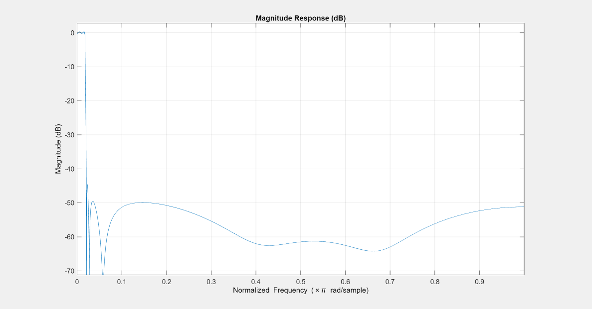
Generate a least P-norm optimal IIR lowpass filter using the iirlpnorm function. Specify a numerator order of 10 and a denominator order of 6. The function returns the coefficients both in the vector form and in the second-order sections (SOS) form. The output argument g specifies the overall gain of the filter when expressed in the second-order sections form.

[b,a,~,sos,g] = iirlpnorm(10,6, ...
    [0 0.0175 0.02 0.0215 0.025 1], ...
    [0 0.0175 0.02 0.0215 0.025 1],[1 1 0 0 0 0], ...
    [1 1 1 1 10 10]);

Visualize the magnitude response of the filter.

fvtool(b,a)

Figure Figure 1: Magnitude Response (dB) contains an axes object. The axes object with title Magnitude Response (dB), xlabel Normalized Frequency ( times pi blank rad/sample), ylabel Magnitude (dB) contains an object of type line.

Transform Filter Using iirlp2lp

Transform the passband of the lowpass IIR filter using the iirlp2lp function. Specify the filter as a vector of numerator and denominator coefficients.

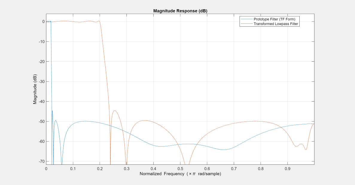
To generate a lowpass filter whose passband extends out to 0.2π rad/sample, select the frequency in the lowpass filter at 0.0175π, the frequency where the passband starts to roll off, and move it to the new location.

Moving the edge of the passband from 0.0175π to 0.2π results in a new lowpass filter whose peak response in-band is the same as in the original filter, with the same ripple and the same absolute magnitude. The rolloff is slightly less steep and the stopband profiles are the same for both filters. The new filter stopband is a "stretched" version of the original, as is the passband of the new filter.

wc = 0.0175;
wd = 0.2;
[num,den] = iirlp2lp(b,a,wc,wd);

Compare the magnitude response of the filters.

hvft = fvtool(b,a,num,den);
legend(hvft,"Prototype Filter (TF Form)", ...
    "Transformed Lowpass Filter")

Figure Figure 2: Magnitude Response (dB) contains an axes object. The axes object with title Magnitude Response (dB), xlabel Normalized Frequency ( times pi blank rad/sample), ylabel Magnitude (dB) contains 2 objects of type line. These objects represent Prototype Filter (TF Form), Transformed Lowpass Filter.

Alternatively, you can also specify the input lowpass IIR filter as a matrix of coefficients. Pass the scaled second-order section coefficient matrices as inputs. Apply the scaling factor g to the first section of the filter.

sosg = sos;
sosg(1,1:3) = g*sosg(1,1:3);
[num2,den2] = iirlp2lp(sosg(:,1:3),sosg(:,4:6),wc,wd);

Compare the magnitude response of the filters.

hvft = fvtool(sosg,[num2 den2]);
legend(hvft,"Prototype Filter (Matrix Form)",...
    "Transformed Lowpass Filter")

Figure Figure 3: Magnitude Response (dB) contains an axes object. The axes object with title Magnitude Response (dB), xlabel Normalized Frequency ( times pi blank rad/sample), ylabel Magnitude (dB) contains 2 objects of type line. These objects represent Prototype Filter (Matrix Form), Transformed Lowpass Filter.

Copyright 2012–2023 The MathWorks, Inc.

Input Arguments

collapse all

Numerator coefficients of the prototype lowpass IIR filter, specified as either:

  • Row vector –– Specifies the values of [b0, b1, …, bn], given this transfer function form:

    H(z)=B(z)A(z)=b0+b1z1++bnzna0+a1z1++anzn,

    where n is the order of the filter.

  • Matrix –– Specifies the numerator coefficients in the form of an P-by-(Q+1) matrix, where P is the number of filter sections and Q is the order of each filter section. If Q = 2, the filter is a second-order section filter. For higher-order sections, make Q > 2.

    b=[b01b11b21...bQ1b02b12b22...bQ2b0Pb1Pb2PbQP]

    In the transfer function form, the numerator coefficient matrix bik of the IIR filter can be represented using the following equation:

    H(z)=k=1PHk(z)=k=1Pb0k+b1kz1+b2kz2++bQkzQa0k+a1kz1+a2kz2++aQkzQ,

    where,

    • a –– Denominator coefficients matrix. For more information on how to specify this matrix, see a.

    • k –– Row index.

    • i –– Column index.

    When specified in the matrix form, b and a matrices must have the same number of rows (filter sections) Q.

Data Types: single | double
Complex Number Support: Yes

Denominator coefficients for a prototype lowpass IIR filter, specified as one of these options:

  • Row vector –– Specifies the values of [a0, a1, …, an], given this transfer function form:

    H(z)=B(z)A(z)=b0+b1z1++bnzna0+a1z1++anzn,

    where n is the order of the filter.

  • Matrix –– Specifies the denominator coefficients in the form of an P-by-(Q+1) matrix, where P is the number of filter sections and Q is the order of each filter section. If Q = 2, the filter is a second-order section filter. For higher-order sections, make Q > 2.

    a=[a01a11a21aQ1a02a12a22aQ2a0Pa1Pa2PaQP]

    In the transfer function form, the denominator coefficient matrix aik of the IIR filter can be represented using the following equation:

    H(z)=k=1PHk(z)=k=1Pb0k+b1kz1+b2kz2++bQkzQa0k+a1kz1+a2kz2++aQkzQ,

    where,

    • b –– Numerator coefficients matrix. For more information on how to specify this matrix, see b.

    • k –– Row index.

    • i –– Column index.

    When specified in the matrix form, a and b matrices must have the same number of rows (filter sections) P.

Data Types: single | double
Complex Number Support: Yes

Frequency value to transform from the prototype filter, specified as a real positive scalar. Frequency wo must be normalized to be between 0 and 1, with 1 corresponding to half the sample rate.

Data Types: single | double

Desired frequency location in the transformed target filter, specified as a real positive scalar. Frequency wt must be normalized to be between 0 and 1, with 1 corresponding to half the sample rate.

Data Types: single | double

Output Arguments

collapse all

Numerator coefficients of the transformed lowpass filter, returned as one of the following:

  • Row vector of length n+1, where n is the order of the input filter. The num output is a row vector when the input coefficients b and a are row vectors.

  • P-by-(Q+1) matrix, where P is the number of filter sections and Q is the order of each section of the transformed filter. The num output is a matrix when the input coefficients b and a are matrices.

Data Types: single | double
Complex Number Support: Yes

Denominator coefficients of the transformed lowpass filter, returned as one of the following:

  • Row vector of length n+1, where n is the order of the input filter. The den output is a row vector when the input coefficients b and a are row vectors.

  • P-by-(Q+1) matrix, where P is the number of filter sections and Q is the order of each section of the transformed filter. The den output is a matrix when the input coefficients b and a are matrices.

Data Types: single | double

Numerator coefficients of the mapping filter, returned as a row vector.

Data Types: single | double

Denominator coefficients of the mapping filter, returned as a row vector.

Data Types: single | double

More About

collapse all

Lowpass IIR Filter to Different Lowpass Filter Transformation

Lowpass IIR filter to different lowpass filter transformation takes a selected frequency from your lowpass filter, wo, and maps the corresponding magnitude response value onto the desired frequency location in the transformed lowpass filter, wt. Note that all frequencies are normalized between zero and one and that the filter order does not change when you transform to the target lowpass filter.

When you select wo and designate wt, the transformation algorithm sets the magnitude response at the wt values of your bandstop filter to be the same as the magnitude response of your lowpass filter at wo. Filter performance between the values in wt is not specified, except that the stopband retains the ripple nature of your original lowpass filter and the magnitude response in the stopband is equal to the peak response of your lowpass filter. To accurately specify the filter magnitude response across the stopband of your bandpass filter, use a frequency value from within the stopband of your lowpass filter as wc. Then your bandstop filter response is the same magnitude and ripple as your lowpass filter stopband magnitude and ripple.

The fact that the transformation retains the shape of the original filter is what makes this function useful. If you have a lowpass filter whose characteristics, such as rolloff or passband ripple, particularly meet your needs, the transformation function lets you create a new filter with the same characteristic performance features.

In some cases transforming your filter may cause numerical problems, resulting in incorrect conversion to the target filter. Use fvtool to verify the response of your converted filter.

References

[1] Nowrouzian, B., and A.G. Constantinides. “Prototype Reference Transfer Function Parameters in the Discrete-Time Frequency Transformations.” In Proceedings of the 33rd Midwest Symposium on Circuits and Systems, 1078–82. Calgary, Alta., Canada: IEEE, 1991. https://doi.org/10.1109/MWSCAS.1990.140912.

[2] Nowrouzian, B., and L.T. Bruton. “Closed-Form Solutions for Discrete-Time Elliptic Transfer Functions.” In [1992] Proceedings of the 35th Midwest Symposium on Circuits and Systems, 784–87. Washington, DC, USA: IEEE, 1992. https://doi.org/10.1109/MWSCAS.1992.271206.

[3] Constantinides, A.G.“Spectral transformations for digital filters.” Proceedings of the IEEE, vol. 117, no. 8: 1585-1590. August 1970.

Extended Capabilities

C/C++ Code Generation
Generate C and C++ code using MATLAB® Coder™.

Version History

Introduced in R2011a

See Also

Functions