Prepare Custom UAV Vehicle Mesh for Unreal Engine Scenario Simulation
You can configure a custom UAV vehicle mesh for use in Unreal Engine simulations by using
the UAV Toolbox Interface for Unreal Engine® Projects. To use your custom UAV vehicle mesh for Unreal Engine simulations, you must configure the mesh with the correct part names and bone
hierarchy, and export the mesh to the .fbx file format.
Note
This topic shows you how to configure your custom UAV vehicle mesh using Blender® Version 4.5. However, you can use other 3D computer graphics software tools that can export meshes in the
.fbxfile format.For details on how to install the UAV Toolbox Interface for Unreal Engine Projects, see Install Support Package for Customizing Scenes.
Assign Names to UAV Vehicle Mesh Parts
Import your custom UAV vehicle mesh file into Blender, and then assign these names to the UAV vehicle mesh parts.

This table indicates which UAV vehicle mesh parts require specific names, and what those names are. Note that, because the Simulation 3D UAV Vehicle block supports only up to eight motor-rotor pairs, you cannot specify names for more than eight motors and eight rotors. For any UAV vehicle mesh parts not included in this table, such as wings and control surfaces, you can specify any name.
| UAV Vehicle Mesh Part | Name |
|---|---|
| UAV body | UAV_body |
| UAV motor | UAV_Motor1, UAV_Motor2, … ,
UAV_Motor8 |
| UAV rotor blade | UAV_Rotor1, UAV_Rotor2, … ,
UAV_Rotor8 |
| Camera pivot point | UAV_CameraPivot |
| Camera arm | UAV_CameraArm |
Configure Bone Hierarchy
Configure your custom UAV vehicle mesh parts with this hierarchy:
UAV_bodyis the parent of all other UAV objects.Each
UAV_Motornobject is the parent of the correspondingUAV_Rotornobject.The
UAV_CameraPivotobject is the parent of theUAV_CameraArmobject.
This diagram illustrates the bone hierarchy.

Note
Your custom UAV vehicle mesh does not need to contain every part, but if you include a part that is a child of another part the hierarchy must also contain the corresponding parent part. For instance, if you want to use a camera arm in your UAV, you must also create a corresponding camera pivot.
Export Mesh and Armature
Once you have configured your mesh part names and their hierarchy, export your mesh to
the .fbx file format.
To export your mesh from Blender, select the entire mesh, then select File, then Export, and then FBX (.fbx). Specify these options in the corresponding pane of the export menu:
In the Object Types pane, select Armature and Mesh.
In the Transform pane, specify these values:
Scale —
1.00.Apply Scalings —
All Local.Forward —
X Forward.Up —
Z Up.Select Apply Unit.
In the Geometry pane, specify these values:
Smoothing —
Face.Select Apply Modifiers.
In the Armature pane, specify these values:
Primary Bone Axis —
X Axis.Secondary Bone Axis —
Z
                            Axis
.
After you have specified these options, select Export FBX.
Launch Unreal Editor from Simulink
To run an Unreal Engine scenario simulation, your Simulink model must contain a Simulation 3D UAV Vehicle block, and a Simulation 3D Scene Configuration block.
To establish a connection between your Simulink model and the Unreal Editor, you must open the Unreal Editor using the Simulation 3D Scene Configuration block. Open the Simulation 3D Scene Configuration block and specify these parameters:
Scene source —
Unreal
                        Editor
Project — Path of the
AutoVrtlEnvproject that comes installed with the UAV Toolbox Interface for Unreal Engine Projects
To launch Unreal editor, Click Open Unreal Editor.

Import Mesh into Unreal Editor
To import your custom mesh into Unreal Editor:
In the Content Browser pane of the Unreal Editor, select Add, and then select New Folder. Create a folder for your custom mesh.
Select Add again, then select Import to folder, where folder is the name of the folder you created for your custom mesh. In the window that opens, select the
.fbxfile that you want to import.In the FBX Import Options dialog box, select Skeletal Mesh. Open the Skeleton drop-down list, select the settings gear icon, select both Show Engine Content and Show Plugin Content, then select UAV_Skeleton.
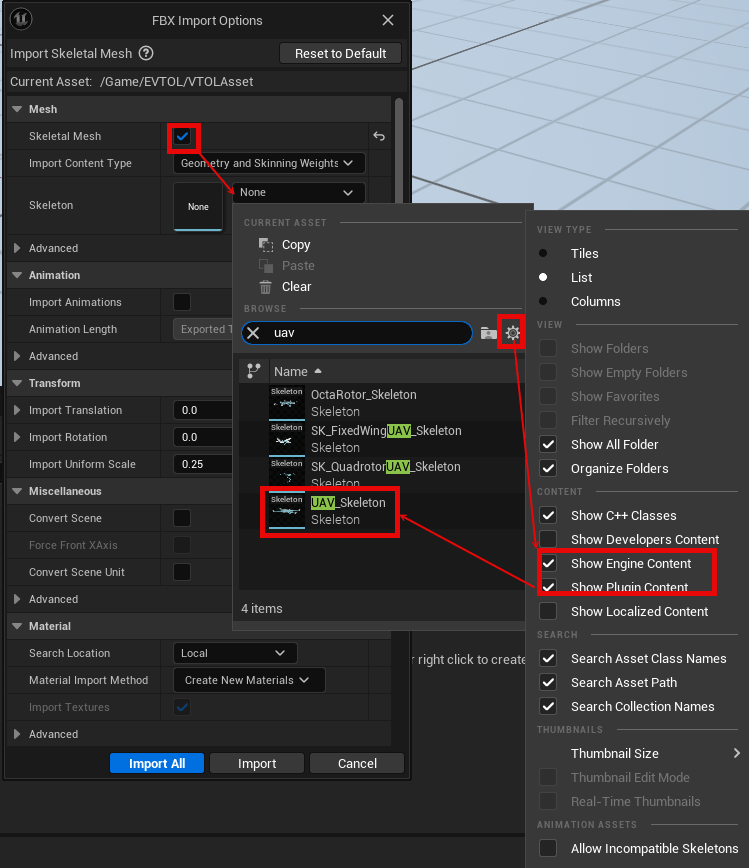
Select Import All.
In the Content Browser pane, double-click the mesh that you have imported to open the Asset Details menu.
In the Material Slots pane of the Asset Details menu, specify the Slot Name of the element that corresponds to the UAV body as
VehicleBody, then save your changes by clicking Save This Asset .
Configure Simulation 3D UAV Vehicle Block
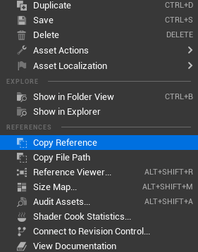
To configure the Simulation 3D UAV Vehicle block to use the custom mesh that you have imported to Unreal Editor, first copy the reference to the mesh by right-clicking the mesh in the Content Browser pane and selecting Copy Reference.
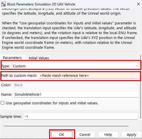
Open the block mask of the Simulation 3D UAV Vehicle block. Set the
Type parameter to Custom, and paste the
reference to the mesh in the Path to custom mesh parameter. Click
OK to save your changes.
Start Simulation
To start the simulation:
In the Content Browser of Unreal Editor, navigate to the Maps folder, then double-click the scene in which you want to run the simulation.
In the Simulink model that contains the Simulation 3D Scene Configuration and Simulation 3D UAV Vehicle blocks, select Run
 . The Simulink model remains in the
Initialize state until you run the scene in Unreal
Editor.
. The Simulink model remains in the
Initialize state until you run the scene in Unreal
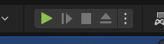
Editor.In Unreal Editor, click Play to run the scene.
For an example of running an Unreal Engine scenario simulation with a custom UAV mesh, see the Visualize VTOL UAV Takeoff and Forward Transition example.
See Also
Simulation 3D Scene Configuration | Simulation 3D UAV Vehicle
Topics
- Unreal Engine Simulation Environment Requirements and Limitations
- Coordinate Systems for Unreal Engine Simulation in UAV Toolbox