Control Rotary Encoder Knob Using STMicroelectronics Nucleo Board
This example shows how to use the Simulink Coder® Support Package for STMicroelectronics STM32 Nucleo board to control a 12-step rotary encoder with a built-in push button.
The example helps you create a custom device driver block that provides access to hardware board features such as communication protocols and hardware libraries.
This example is created with the intention to help users create a custom device driver block that provide easy access to hardware board features such as communication protocols or hardware libraries, not available in the support package.
After creating a custom device driver block for the Encoder Timer module as available on the STM32 F7/F4 devices, you can deploy the same to the hardware. The block appears in the example model stmnucleo_encoder_position_read.slx. The block reports the direction and position information of an Arduino Encoder module that is connected to a STM32 F401RE Nucleo board.
For more information about creating a custom device driver block by using a system object, see:
Device Driver Blocks (Embedded Coder)
By using a similar approach as described, you can design and develop a custom Encoder driver block to extend support in the support package.
Use these files to implement the driver block:
soc_stm_encoder.cppandsoc_stm_encoder.h-- These files define the device specific device specific Initialization, Configuration as well as runtime routines to read encoder count, index count, and index pulse for the Encoder in a source file.EncoderBlock.m-- This M script implements the MATLAB system object that defines the block properties and implements the setup(init) and step(runtime) routines by using the driver API that are defined in the source files.stmnucleo_encoderlib.slx-- This library contains the final driver block. By using this library, you can share the block with others.
Hardware Requirements
Hardware Setup
The connection and block mask images show that:
Connect Nucleo pin PA_8 to Encoder pin A (CLK).
Connect Nucleo pin PA_9 to Encoder pin B (DT).
Connect Nucleo pin GND to Encoder pin GND.
Connect Nucleo pin ‘+’ to Encoder pin 5V..

Running the Example
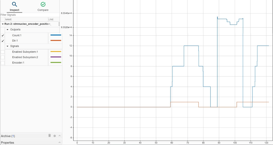
The example uses the Encoder device driver block and adds logic to report the direction of the encoder by using the encoder count information from the block. The block reports direction as '1' or '0', depending on the direction of rotation of the knob. You can also observe the direction in the Simulation Data Inspector as shown in the image. The image shows when the count rolls over for a count < 0 to 65535, but the direction continues to report the same value as the knob continued to be rotated in the same direction.
You can also select a web site from the following list:
Americas
- América Latina (Español)
- Canada (English)
- United States (English)
Europe
- Belgium (English)
- Denmark (English)
- Deutschland (Deutsch)
- España (Español)
- Finland (English)
- France (Français)
- Ireland (English)
- Italia (Italiano)
- Luxembourg (English)
- Netherlands (English)
- Norway (English)
- Österreich (Deutsch)
- Portugal (English)
- Sweden (English)
- Switzerland
- United Kingdom (English)