Square Path Navigation Using Encoder with the VEX Microcontroller
This example shows you how to use Simulink® Coder™ Support Package for ARM® Cortex®-based VEX® Microcontroller to interface VEX Integrated Encoder Module to the VEX Microcontroller and use the sensor data to control a 4-wheeled robot.
Introduction
Simulink Coder Support Package for ARM Cortex-based VEX Microcontroller enables you to create and run Simulink models on a VEX microcontroller.
In this example, you will learn how to verify the output of Integrated Encoder Module block and create a model that reads the output of the encoder and use this value to control the motion of a 4-wheeled robot. The 4 wheels are powered by 2 DC motors which are connected to a VEX Microcontroller. The Simulink model will read the rotation tick count from the encoder and provide appropriate speed input to the DC motors to drive the robot to trace a square path.
Prerequisites
If you are new to Simulink, we recommend watching the Simulink Quick Start video.
We recommend completing Getting Started with VEX Microcontroller Support Package.
Required Hardware
To run this example you will need the following hardware:
ARM Cortex-based VEX Microcontroller
VEX Integrated Encoder Modules (2)
VEXnet Gamepad and VEXnet keys
Standard DC Motors (2) and Motor Controller 29 (2)
4-wire Cable (2)
4-wheel robot platform
7.2V Battery
USB type A-Male to A-Male cable
Verification of Integrated Encoder Module Block
In this task, you will learn how to use the Integrated Encoder Module block in a Simulink model and verify the block output using Monitor and Tune action.
Task 1 - Hardware Connections
Below is a figure of hardware setup with Integrated Encoder Module connected to the VEX Microcontroller for verification in External mode simulation.
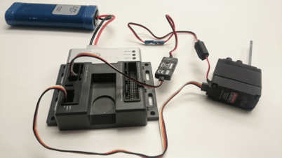
1. Connect the VEX Microcontroller to your computer with a USB cable.
2. Install the Integrated Encoder Module on the motor as given here.
3. Plug one end of a 4-wire cable to the DC motor and the other end to the I2C port on the VEX Microcontroller.
4. Connect the DC motor to motor pin 3 on the VEX microcontroller. Use the Motor Controller 29 cable to establish the connection between the motor leads and the pin on VEX Microcontroller. Connect them as described on Page 4 of the VEX Microcontroller and VEXnet Joystick User Guide.
5. Connect the battery supply to the VEX Microcontroller.
Task 2 - Configure a Simulink model for parameter tuning and verify the Encoder block
In this task, you will configure a Simulink model for parameter tuning to read the rotation of the DC Motor using the Integrated Encoder Module and display it on the Display block.
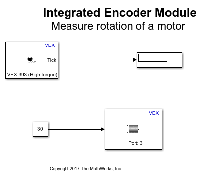
1. Open the pre-configured vexarmcortex_shaftencoder_externalmode model. In this model, the output of the encoder block is connected to the input of a Display block. Make sure that the parameter value for Sequence order from I2C port for the encoder block is according to the sensor connection in Task 1. A Constant block provides a speed input of 30 to the DC Motor block.
2. See Signal Monitoring and Parameter Tuning to prepare and run this model for parameter tuning.
3. While the model is running, observe the tick count value in Display block. Try specifying a negative value for the motor speed using the Constant block and observe the tick count value. Observe that the tick value increases for anti-clockwise rotation and decreases for clockwise rotation.
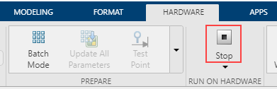
4. In the Hardware tab, click Stop to terminate the Monitor and Tune action.
In Task 1 and 2, you learned how to connect the VEX Integrated Encoder Module to the VEX microcontroller and verify the tick value read by the encoder block in External mode simulation.
Square Path Navigating Robot Using Integrated Encoder Module
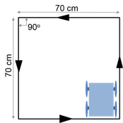
In this task, you will learn how to use the encoder to control the motion of a 4-wheeled robot to trace a square path. The robot moves in a straight line for 70 cm, takes a left turn and repeats these two steps 4 times until a square path is traced as shown in the figure below.
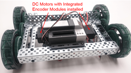
Below is a figure of a 4-wheel robot platform with Integrated Encoder Modules installed on 2 DC motors. The DC motors are connected to the 2 wheels and attached to a VEX microcontroller.
Task 3 - Hardware Connections
1. The two DC motors drive the left and right set of wheels on the robot platform. Perform all the steps mentioned in Task 1 above for the DC motor attached to left wheel.
2. Install the Integrated Encoder Module on the 2nd DC motor attached to right wheel as given here.
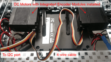
3. Plug one end of a 4-wire cable to the 1st DC Motor and the other end to the 2nd DC motor as shown in the figure below.
4. Connect the motor attached to the left wheel to motor pin 3, and the motor attached to the right wheel to motor pin 6. Use the Motor Controller 29 cables to establish the connection between the motors leads and the pins on VEX Micrcontroller. Connect them as described on Page 4 of the VEX Microcontroller and VEXnet Joystick User Guide.
Task 4 - Build and download the Simulink model for Square Path Navigating Robot using Encoder
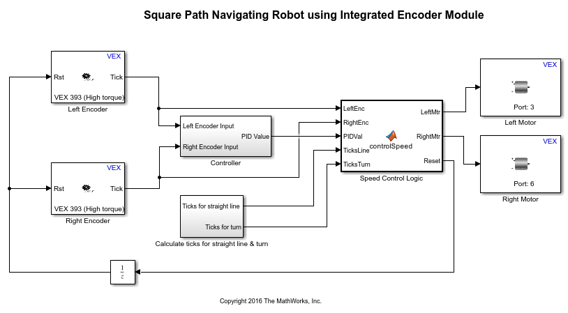
In this task, you will learn a way to model the logic for using the encoder output to control the speed of the two DC motors, thereby controlling the motion of the robot. The logic for controlling the motors is implemented in a MATLAB Function block. You will then build and download the model to the VEX microcontroller.
1. Open the pre-configured vexarmcortex_iem_navigate model.
2. Note the following points in the Simulink model:
The parameter values Sequence order from I2C port for Integrated Encoder Module blocks in the model are as per the hardware connections in Task 3. The parameter Motor Channel for the Left Motor block is chosen as '3' and for the Right Motor block as '6' as per the hardware connections in Task 3.
The encoders connected to left and right wheels of the robot are referred to as Left Encoder and Right Encoder respectively. The difference between the tick count read by the left and right encoders is calculated and fed to a PID controller in the subsystem Controller. The PID output is used to control the input speed given to the DC motors during straight line motion to counter the effect of wheel drifting and keep the robot on a relatively straight path.
The ticks required to move a specified distance on a straight line and the ticks for a specified degree of turn are calculated in the subsystem Calculate ticks for straight line & turn as shown below.

The value of ticks per rotation can be obtained from the type of encoder that is being used. The distance covered in 1 rotation is obtained from the circumference of robot wheel to which the encoder is connected.
Assuming  is the robot wheel radius in cm and
  is the number of ticks per rotation,

The number of ticks to travel a distance  cm on a straight line can be calculated as:

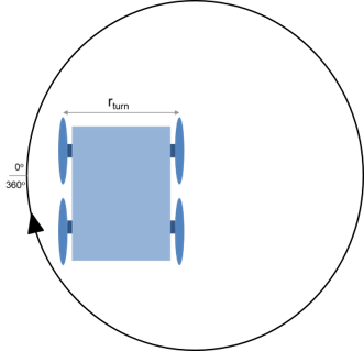
Assuming that one of the motors attached to the wheels is stationary and the other motor rotates, the turning radius  of the robot is roughly equal to the robot width or wheel to wheel distance of the robot. Then, the distance covered for a 360 degree turn is equal to the circumference of circle with radius equal to the robot turning radius as shown below.
Therefore, distance covered for  degree turn can be calculated as:

The number of ticks to take a turn of degrees can be calculated as:

If the two motors on the robot are made to rotate in opposite directions, the center of rotation for the robot will be halfway between the robot wheels and therefore, the turning radius of the robot will be reduced to half of the wheel to wheel distance. Subsequently, the number of ticks required for degree of turn will be reduced to half of the value calculated above.
Based on the robot platform and the encoder that you use for this example, you may require to change the values of robot wheel radius, wheel to wheel distance of the robot and ticks per rotation specified in Constant blocks in the subsystem Calculate ticks for straight line & turn
The left and right encoder tick values, PID output and the number of ticks required for straight line and turn are given as inputs to the MATLAB Function block. This block defines the logic for controlling the speed input to left and right motors, thereby controlling the robot navigation. See Create Model That Uses MATLAB Function Block for an example of using the MATLAB Function block.
The motors are provided a speed controlled by the PID output for straight line motion. Once the tick count reaches the value for specified distance, the encoder value is reset by making the Reset output from the MATLAB Function block high. The motors are then provided with a constant speed in opposite directions so that the robot takes a turn until the tick count reaches the value for 90 degrees of turn and the encoder value is reset. This process is repeated four times so that the robot completes a square path.
The Reset output from the MATLAB Function block is provided to the encoder blocks through a Unit Delay block to avoid an algebraic loop. An algebraic loop occurs when the block output depends on the input value and the input directly controls the output value. See Algebraic Loops for details on Algebraic loops. The presence of this Unit Delay block will cause a delay of one time step for the encoder value to be reset to 0.
3. In the Simulink model, go to the Modeling tab and click Model Settings.

4. When the Configuration Parameters page opens up, navigate to the Hardware Implementation pane.
Set the Hardware board to ARM Cortex-based VEX Microcontroller.
5. In the Configuration Parameters page, navigate to Solver pane and set the Solver to discrete (no continuous states).
6. Click OK.
7. Before building the model, make sure to connect the VEX Microcontroller to your computer with a USB A-Male to A-Male cable.
8. In the Simulink model, go to the Hardware tab and click Build, Deploy & Start. The model will now be deployed to the VEX microcontroller.

9. Disconnect the USB cable from the VEX microcontroller and connect the VEXnet key to the VEX microcontroller. Turn ON the VEX microcontroller and Gamepad and place the robot on a surface where it will be able to complete a square path without encountering any obstacles. Once the VEXnet keys are paired, the robot begins to move and trace the specified path. Note that the number of ticks required for moving a certain distance on a straight line and for taking a specified degree of turn may vary slightly based on the surface on which the robot moves and the battery level. You may need to modify the required tick count slightly so that the robot is able to trace a square path on the desired surface.
Other Things to Try
Perform the same exercise using Optical Shaft Encoder by replacing Integrated Encoder Module blocks. You can use the preconfigured models for Verification of Optical Shaft Encoder block, vexarmcortex_shaftencoder_externalmode and Square Path Navigating Robot using Optical Shaft Encoder, vexarmcortex_shaftencoder_navigate. Given below are the required hardware connections if you use the preconfigured models.
Insert the shafts of DC motors connected to left and right wheels through the Optical Shaft Encoders.
Plug the top wire of the left encoder to digital port 1 on the VEX Microcontroller.
Plug the bottom wire of the left encoder to digital port 2 on the VEX Microcontroller. Place the encoder such that its removable side is facing up to identify the top and bottom wires of the encoder.
Plug the top wire of the right encoder to digital port 3 on the VEX Microcontroller.
Plug the bottom wire of the right encoder to digital port 4 on the VEX Microcontroller.
You can also select a web site from the following list:
Americas
- América Latina (Español)
- Canada (English)
- United States (English)
Europe
- Belgium (English)
- Denmark (English)
- Deutschland (Deutsch)
- España (Español)
- Finland (English)
- France (Français)
- Ireland (English)
- Italia (Italiano)
- Luxembourg (English)
- Netherlands (English)
- Norway (English)
- Österreich (Deutsch)
- Portugal (English)
- Sweden (English)
- Switzerland
- United Kingdom (English)