Tap-Changing Transformer for Automatic Voltage Regulation
This example shows how to use a single-phase tap-changing transformer to control the voltage across an RLC load. The system contains an AC voltage source that generates a 60 Hz sine wave (located on the left-hand side of the circuit). The root-mean-square value for the voltage generated by this source is 120 V (reference voltage).
The Feedback Controller uses the peak voltages across the AC voltage source and RLC load to generate the control signal provided to the tap-changing transformer.
The tap-changer location is on the transformer's secondary winding. The values defined for the maximum and minimum voltages across the RLC load are 1.01 and 0.99 of the reference voltage, respectively. The tap-changing transformer has 33 positions for the tap setting, between -16 and +16, including the 0 position that corresponds to the nominal tap position. The nominal turns ratio (primary/secondary) is 0.9.
The step voltage per tap change is 1.5% of the transformer's primary voltage. The sample time is 1e-5 seconds.
Model

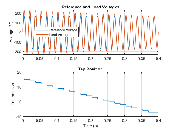
Simulation Results from Simscape Logging
The plot below shows the simulated voltages across the AC voltage source and RLC Load and the evolution of the tap position.
