Power Converter Voltage Stabilizer
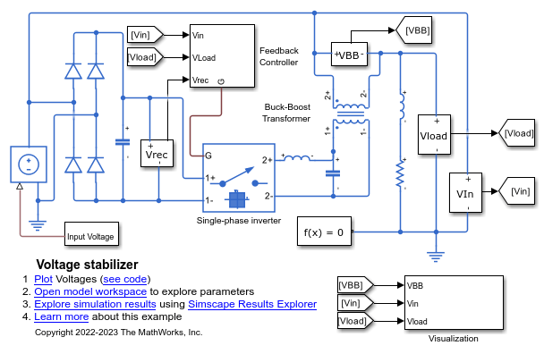
This example shows a voltage stabilizer circuit. It uses a full-wave rectifier, a single-wave inverter, and a buck-boost transformer to achieve voltage regulation.
If the load sensor detects a voltage disparity, the feedback controller drives the four-quadrant chopper as a single-phase inverter and generates a voltage equal to the difference between the nominal value and the measured one. This output is either in phase or 180 degrees out of phase with the incoming voltage and is supplied to the primary winding of the transformer. The induced voltage in the secondary winding of the buck-boost transformer is added to the line, supplying the load with a constant voltage.
Model Overview
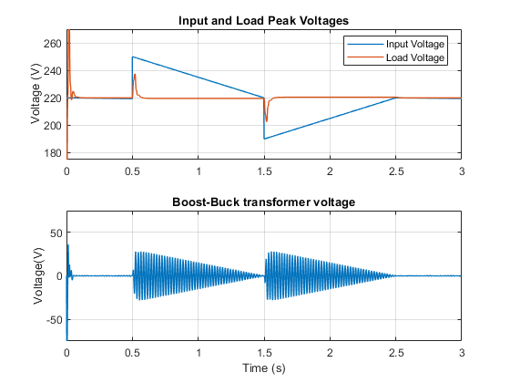
Simulation Results
The plot below shows the peak values of the input and load voltage. It also shows the voltage induced in the secondary winding of the buck-boost converter.
Results from Real-Time Simulation
This example has been tested on these platforms:
Speedgoat™ Performance real-time target machine with an Intel® 3.5 GHz i7 multi-core CPU and 4 GB RAM.
dSPACE® SCALEXIO LabBox with Intel® Core XEON E3-1275v3 at 3.5GHz and 4 GB RAM.
You can run this model in real time with a step size of 30 microseconds by using the Simscape local solver. For small sample rates, a task overrun might occur during the initial task execution due to a cold cache. To avoid this overrun, if the selected platform supports these options, relax the start-up behavior by specifying a limited number of task overruns or increasing the sample time of periodic tasks during the start-up phase of the real-time application.