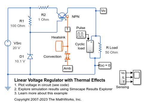
Linear Voltage Regulator with Thermal Effects
This example shows a low-cost voltage regulator circuit whose performance depends on both load current and temperature. Bias resistor R1 ensures that the voltage at the transistor base is close to the rated zener voltage. The regulator output voltage is also approximately at this voltage, the base-emitter voltage being a few tenths of a volt. The precise base-emitter voltage depends on the transistor working point (which in turn depends on the load) and also the temperature. Resistor R2 only serves to provide some protection in the event of a transient output short circuit.
You can use this model to validate that selected circuit components result in an adequate level of voltage regulation. You can also use it to size the heatsink that keeps the transistor junction temperature within the permitted operating range. By modeling both electrical and thermal properties, you understand the trade-offs between the electrical and thermal parameter choices.
You can achieve better regulation by using feedback. For more information, see Linear Voltage Regulator with Feedback.
Model
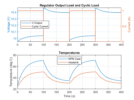
Simulation Results from Simscape Logging
The plot below shows the output of the voltage regulator holding close to the desired output of 10 V. It also shows the temperature of the NPN case and its heatsink as the cyclic load turns on and off.
Results from Real-Time Simulation
This example has been tested on these platforms:
Speedgoat™ Performance real-time target machine with an Intel® 3.5 GHz i7 multi-core CPU and 4 GB RAM.
dSPACE® SCALEXIO LabBox with Intel® Core XEON E3-1275v3 at 3.5GHz and 4 GB RAM.
You can run this model in real time with a step size of 50 microseconds by using the Simscape local solver. For small sample rates, a task overrun might occur during the initial task execution due to a cold cache. To avoid this overrun, if the selected platform supports these options, relax the start-up behavior by specifying a limited number of task overruns or increasing the sample time of periodic tasks during the start-up phase of the real-time application.
See Also
NPN Bipolar Transistor | Diode