Lead Screw Joint
Joint with coupled rotational and translational degrees of freedom

Libraries:
Simscape /
Multibody /
Joints
Description
The Lead Screw Joint block represents a joint that has one degree of freedom and models a pair of coupled rotation and translation, as shown in the image.

During simulation, the joint constrains the z-axes of the base and follower frames to be aligned. The follower frame origin can translate along the base z-axis while the follower x-axis and y-axis rotate about the base frame z-axis. The translation is proportional to the rotation based on the value of the Lead and Direction parameters.
To specify the target of the initial state for the joint, use the parameters under State Targets. You can specify the targets based on the relative rotation or translation between the joint frames. To specify the joint mode configuration, use the Mode parameter. For more details, see Mode Configuration under the Ports and Parameters sections.
The joint block has ports that output sensing data, such as position, velocity, acceleration, force, and torque, that you can use to perform analytical tasks on a model.
Faults
Using mode faults, you can change the joint modes during a simulation without modifying the
model design. The fault injection overrides the mode setting. For example, if a joint has
the Mode parameter set to Locked and the
Fault behavior parameter set to Disengaged, the
joint becomes disengaged.
To add a mode fault to a joint block, click on the joint block, in the Simscape Block tab, and the Faults section,
click Fault > Add Fault.
Alternatively, you can click the joint block, hover over the ellipsis to open the action
bar, and click the Add a fault on the block icon ![]() . You can add multiple faults to a joint block, but the
joint block can have only one active fault during a simulation.
. You can add multiple faults to a joint block, but the
joint block can have only one active fault during a simulation.
As you add faults, in the Property Inspector, under the Fault
section, specify the behavior and the trigger type of the fault. To define the fault
behavior, click the link next to the Fault Behavior. This
joint supports Locked, Normal, or
Disengaged mode. The joint blocks support these trigger types:
Always on, Timed, Manual, and
Conditional. For more details of these trigger types, see Set Fault Triggers. To trigger a
conditional fault, you can use Simulink signals, Simscape language blocks, and MATLAB
workspace variables. To set the active fault for a block, use the Fault Table. For more
details, see Access the Fault Table and Fault Dashboard.
To enable fault simulation, in the Simscape Block tab and
the Faults section, turn on the Fault
Simulation button. The fault simulation is on when the button is green and
the status is on. The simulation logs the trigger status
data. To view the data, use the Simulation Data
Inspector. Also, you can see the fault status and a summary of the triggered
faults in the Fault Dashboard. To open the Fault Dashboard, in the Simscape Block tab, click Faults >
Fault Dashboard.
To create and modify faults, you can also use Simscape™ and Simulink® fault functions. For more details, see the function section of the Simulink Fault Controls and Simscape Faults Interface.
Examples

Lead Screw with Friction
Models a lead screw with friction. The constraint force in the lead screw is measured and used to calculate the friction torque within the lead screw. A continuous stick-slip friction model is used to determine the coefficient of friction based on the relative rotational speed of the two parts connected by the lead screw.
Cartesian 3-D Printer
Models a Cartesian 3-D printer. The model allows you to specify the rotational motion of the motor on each axis to define a printing path. In this example, the printing head moves along the edges of two letters, S and M, using the predefined rotational motions.
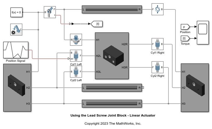
Using the Lead Screw Joint Block - Linear Actuator
Illustrates the use of the Lead Screw Joint block to model a linear actuator. The Lead Screw Joint block converts rotational motion at the Revolute Joint block to translational motion at the four Cylindrical Joint blocks. The translational motion is specified as a motion input to a cylindrical joint and the necessary actuator torque is automatically computed at the revolute joint.