Model a Multibody System in MATLAB
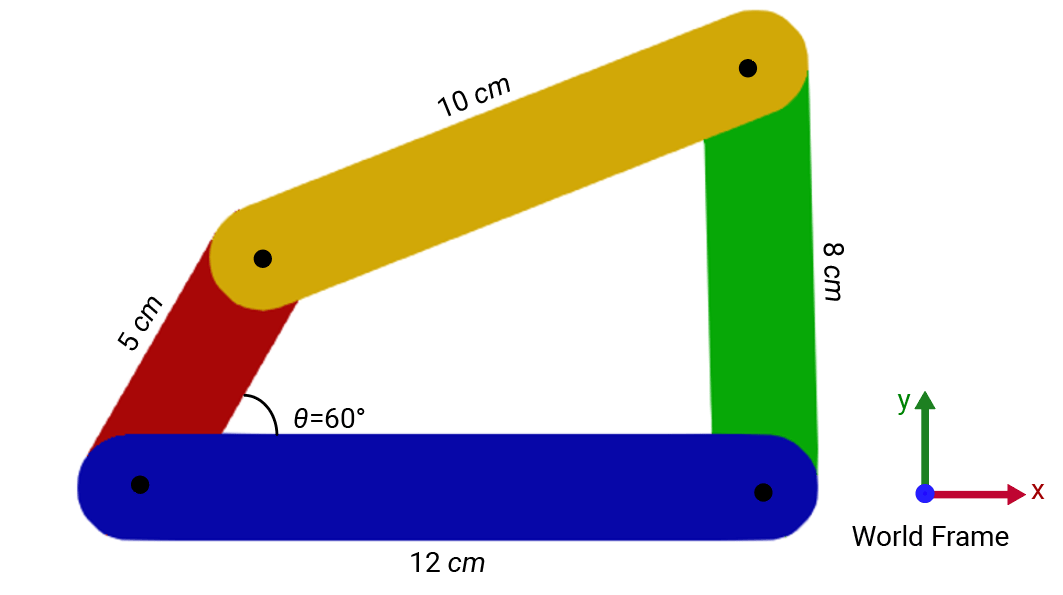
R2026bThis example shows how to model a four-bar system using the MATLAB classes of Simscape Multibody. In this example, you create a crank-rocker mechanism with four links that measure 5 cm, 8 cm, 10 cm, and 12 cm in length.
To avoid typing the namespace name for the classes, use the import function.
import simscape.Value simscape.op.* simscape.multibody.*;
Create a Four-Bar System
First, create a simscape.multibody.Multibody object to represent the four-bar system and name the object fb. A Multibody object is a hierarchical container for component objects. Each component object represents a part or subsystem of the multibody system.
fb = Multibody
fb =
  Multibody:

  No connectors.

  No components.

  No connections.

  Multibody with properties:

     ComponentNames: [0×1 string]
    FrameConnectors: [0×1 string]
The object starts empty and includes zero connectors.
Next, create the links and joints for the four-bar system. Each link of the four-bar system is a rigid body that has two end frame connectors and a reference frame located at the centroid of the body.
To construct links, use the helper function link. For detailed instructions on constructing the link in MATLAB, see the Model a Rigid Body in MATLAB.
First, specify the length and color of each link according to the system diagram. To define length and color, use the simscape.Value object and the simscape.multibody.SimpleVisualProperties class:
bottomLength = Value(12,"cm");
topLength = Value(10,"cm");
leftLength = Value(5,"cm");
rightLength = Value(8,"cm");
bottomColor = SimpleVisualProperties([0 0 .8]);
topColor = SimpleVisualProperties([1 .8 0]);
leftColor = SimpleVisualProperties([.8 0 0]);
rightColor = SimpleVisualProperties([0 .8 0]);
To construct links, use the helper function link with the specified link lengths and colors. The first two arguments set the length and color, and the third argument specifies whether to add a connector to the reference frame of the link. If the third argument is true, the reference frame of the link becomes a frame connector for connecting to other frames or components. The function uses hard-coded values of 2 cm for width and 1 cm for height.
Because the reference frame of the bottom link connects to the world frame, set the third argument for the bottom link to true to expose it as a frame connector.
Bottom_Link = link(bottomLength,bottomColor,true);
Top_Link = link(topLength,topColor,false);
Left_Link = link(leftLength,leftColor,false);
Right_Link = link(rightLength,rightColor,false);
Add the created links to the four-bar system by using the addComponent method.
addComponent(fb,"Bottom_Link",Bottom_Link);
addComponent(fb,"Top_Link",Top_Link);
addComponent(fb,"Left_Link",Left_Link);
addComponent(fb,"Right_Link",Right_Link);
Add the world frame to the four-bar system by using the addComponent method, and connect the reference frame of the bottom link to the world frame by using the connect method.
addComponent(fb,"World",WorldFrame);
connect(fb,"World/W","Bottom_Link/reference");
To assemble the links into the four-bar system, use four revolute joints. To create these joints, use the simscape.multibody.RevoluteJoint class. Name the joints based on their locations and add them to the four-bar system using the addComponent method.
joint = RevoluteJoint;
addComponent(fb,"Bottom_Right_Joint",joint);
addComponent(fb,"Top_Left_Joint",joint);
addComponent(fb,"Top_Right_Joint",joint);
addComponent(fb,"Bottom_Left_Joint",joint);
Connect the links using the revolute joints with the connectVia method.
connectVia(fb,"Bottom_Left_Joint","Bottom_Link/neg_end","Left_Link/neg_end");
connectVia(fb,"Bottom_Right_Joint","Bottom_Link/pos_end","Right_Link/neg_end");
connectVia(fb,"Top_Left_Joint","Top_Link/neg_end","Left_Link/pos_end");
connectVia(fb,"Top_Right_Joint","Top_Link/pos_end","Right_Link/pos_end");
By default, gravity aligns with the negative z-direction of the world frame. In this example, the four-bar system moves on the X-Y plane of the world frame, so gravity must align with the negative y-direction. To specify the gravity for the four-bar system, use the simscape.multibody.UniformGravity class:
gravity = UniformGravity(Value([0 -9.80665 0],"m/s^2"));To set the initial configuration for the four-bar system, specify a target for a joint primitive. For example, set the joint primitive target of the bottom-left joint to 60 degrees by using a simscape.op.OperatingPoint object and a simscape.op.Target.
JointOP = OperatingPoint;
JointOP("Bottom_Left_Joint/Rz/q") = Target(60,"deg","High")
JointOP =
  OperatingPoint with children:

  OperatingPoints:

   ChildId              Size
   ___________________  ____

   'Bottom_Left_Joint'   1x1
Check the components and structure of the system.
fb
fb =
  Multibody:

  No connectors.

  Components:

  Name                  Type
  ____________________  ______________

  "Bottom_Left_Joint"   Revolute Joint
  "Bottom_Link"         Rigid Body
  "Bottom_Right_Joint"  Revolute Joint
  "Left_Link"           Rigid Body
  "Right_Link"          Rigid Body
  "Top_Left_Joint"      Revolute Joint
  "Top_Link"            Rigid Body
  "Top_Right_Joint"     Revolute Joint
  "World"               World Frame

  Connections:

  Connector 1              Connector 2
  _______________________  ______________________

  "Bottom_Left_Joint/B"    "Bottom_Link/neg_end"
  "Bottom_Left_Joint/F"    "Left_Link/neg_end"
  "Bottom_Link/pos_end"    "Bottom_Right_Joint/B"
  "Bottom_Link/reference"  "World/W"
  "Bottom_Right_Joint/F"   "Right_Link/neg_end"
  "Left_Link/pos_end"      "Top_Left_Joint/F"
  "Right_Link/pos_end"     "Top_Right_Joint/F"
  "Top_Left_Joint/B"       "Top_Link/neg_end"
  "Top_Link/pos_end"       "Top_Right_Joint/B"

  Multibody with properties:

     ComponentNames: [9×1 string]
    FrameConnectors: [0×1 string]
Create a Simulink Model
To fully use the capabilities in Simscape Multibody, including the ability to simulate of multibody systems, create a Simulink model from the fb object by using the makeBlockDiagram method.
makeBlockDiagram(fb,JointOP,"FourBar")When you construct a multibody system in MATLAB, Simscape Multibody specifies the state of the joint primitives differently. Instead of specifying the state through joint targets in joint blocks, the fb object uses the simscape.op.OperatingPoint object, JointOP, to define state targets for joint primitives. Therefore, to create a Simulink model from the fb object, the makeBlockDiagram method requires the JointOP and fb objects. The makeBlockDiagram method uses the data in the JointOP object to populate the joint target parameters for the joint blocks in the generated Simulink model.
You can modify the FourBar model just like any Simulink model. However, a best practice is to avoid making changes in the FourBar model that you can also make in the fb object. Instead, make the changes in the code that generates the fb object, regenerate the object, and then create a new Simulink model. This approach ensures that the code remains the primary source for the model.
See Also
simscape.multibody.Component | simscape.multibody.Multibody | simscape.multibody.Joint

