Generate Test Cases for a Simplified Cruise Control Model
With Simulink® Design Verifier™, you can generate test cases for model coverage and custom objectives. You can also measure coverage of existing requirements-based test cases and extend these test cases to increase coverage or achieve full coverage.
This tutorial explains a simplified cruise control model that controls the throttle speed. You generate test cases that satisfy condition and decision model coverage objectives and then, simulate these test cases to generate the model coverage report.
Analyze a Simple Cruise Control Model
Consider a simplified cruise control model that adjusts the throttle to maintain a steady speed as set by the set speed.
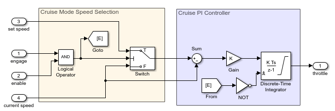
This cruise control model meets these requirements:
The control system is activated when the
engageand theenablesignals aretrue. This condition is defined by the AND block.When the system is activated, the Switch block passes
set speedto the PI controller. The PI controller calculates thethrottleby integrating the error term defined by the differenceset speed - current speed.Throttlecontinues to increase or decrease untilset speedis higher or lower thancurrent speed.When the system is not activated, the Discrete-Time Integrator block resets. The error term is
zero, which means thethrottleis in reset position.
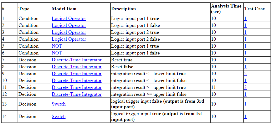
When you perform test generation analysis, Simulink Design Verifier generates test cases for the model coverage objectives associated with each model item in the model. The table lists the condition and decision coverage objectives for the associated Model blocks. For more information on model coverage objectives, see Model Coverage Objectives for Test Generation and Model Objects That Receive Coverage (Simulink Coverage).
| Block | Model Coverage Objective | Generated Test Case Description |
|---|---|---|
| AND | Condition | Each input value is set to true or false independently. |
| NOT | Condition | Input is set to true or false independently. |
| Switch | Decision | Test case demonstrates that the Switch passes both the input signals to output. |
| Discrete-Time Integrator | Decision |
|
Generate Test Cases for Coverage Analysis
The analysis results give detailed descriptions of the coverage objectives for each model item and generated test cases for all satisfied objectives. You simulate the generated test cases to measure model coverage.
Generate Test Cases
1. Open the model sldvexSimpleCruiseControl:
sldvexSimpleCruiseControl
2. On the Design Verifier tab, in the Mode section, select Test Generation.
3. To generate test cases, click Generate Tests.
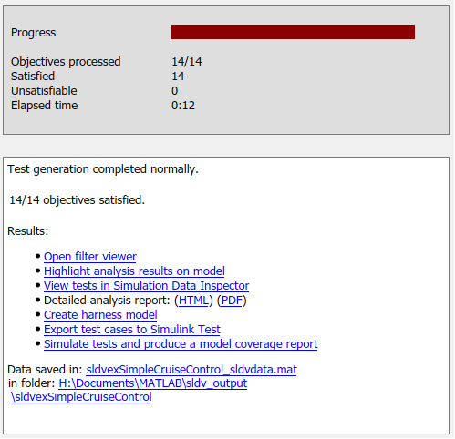
The Results Summary window displays the results. The result indicates that all 14 objectives are satisfied.
Review the Analysis Results
1. On the Design Verifier tab, in the Review Results gallery, click Highlight in Model. The model objectives that the software found to be satisfied are highlighted in green.
Click the Switch block. The Results window displays the summary of the satisfied decision objectives.
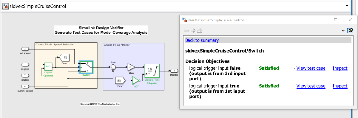
The summary shows that all the objectives of the Switch block are satisfied.
2. To view the HTML report, in the Review Results gallery, click HTML Report.
The test objective status section includes detailed descriptions of satisfied objectives for each model item and generated test case.
Simulate Test Cases for Model Coverage Analysis
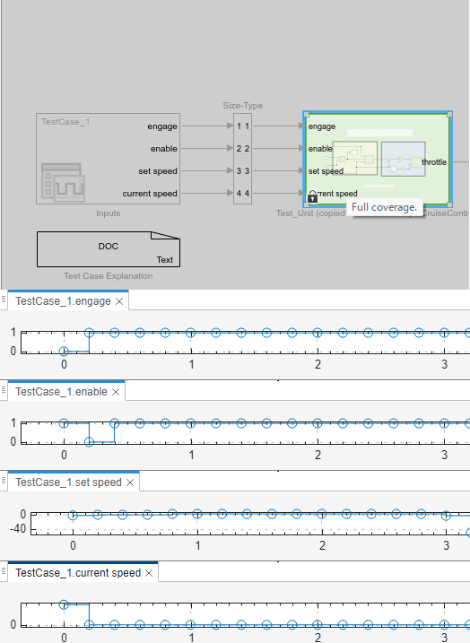
To view the test case for a model coverage objective, in the Results window, click View test case. The harness model and the Signal Editor block opens. To simulate the test case, click *Run all* button. Open Signal Editor block to view the test case.
The software simulates the test case and highlights the harness model. To view the coverage of the model items, point the cursor to each model object in the harness model.
See Also
Design Verifier Pane: Test Generation | Objectives Status Chapters
Related Topics
Select a Web Site
Choose a web site to get translated content where available and see local events and offers. Based on your location, we recommend that you select: United States.
You can also select a web site from the following list
Americas
- América Latina (Español)
- Canada (English)
- United States (English)
Europe
- Belgium (English)
- Denmark (English)
- Deutschland (Deutsch)
- España (Español)
- Finland (English)
- France (Français)
- Ireland (English)
- Italia (Italiano)
- Luxembourg (English)
- Netherlands (English)
- Norway (English)
- Österreich (Deutsch)
- Portugal (English)
- Sweden (English)
- Switzerland
- United Kingdom (English)
Asia Pacific
- Australia (English)
- India (English)
- New Zealand (English)
- 中国
- 日本Japanese (日本語)
- 한국Korean (한국어)