Limit Variant Condition Propagation Within Bounded Regions Using Variant Start and Variant End Blocks
R2026bThis example shows how to use Variant Start and Variant End blocks to create bounded regions in a model where variant conditions apply only to blocks within the region.
Variant conditions are logical expressions that activate or deactivate model components during simulation or code generation. You can switch between different model configurations without altering the model structure. When you apply variant conditions to bounded regions, you restrict the activation and deactivation to a specific set of blocks by preventing the propagation of variant conditions beyond the bounded region.
Use Variant Start and Variant End blocks when:
You need control over where variant condition propagation begins and ends.
Variant logic cannot be contained within a single Variant Subsystem block.
You want to localize variant conditions without modifying the existing model hierarchy.
A region between the output port of a Variant Start block and the corresponding input port of a Variant End block forms a bounded region in the model when these conditions are met:
You can wrap each variant choice in a subsystem without intersecting with other variant choices. There is a clear demarcation between choices.
Each variant choice connects through only one input port (from the Variant Start block output port) and only one output port (to the destination). Choices do not branch out of the region.
Explore the Model
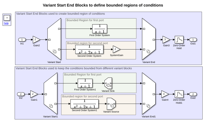
Open the slexVariantStartAndEnd model, which represents a control system. The control system contains first-order and second-order systems inside the bounded regions defined by the Variant Start and Variant End blocks. These blocks determine whether to activate the first-order or the second-order system based on the variant condition that evaluates to true during simulation. The blocks outside this region are unconditional, and remain unaffected by the variant conditions.
model = "slexVariantStartAndEnd";
open_system(model)
Highlight Blocks Within a Bounded Region
Highlight the blocks within each bounded region by using the Start End Bounded Regions option to analyze how different components interact:
On the Debug tab of the toolstrip, select Information Overlays > Start End Bounded Regions.
On the Variant Start End Bounded Regions tab, expand slexVariantStartAndEnd/Variant Start and select Port 2. The blocks within the bounded region of the Variant Start block are highlighted in the Simulink canvas. Alternatively, click the output signal connected to the Variant Start block to highlight the blocks within the bounded region.
Apply Same Variant Conditions to Control Active Choice Within a Bounded Region
You can apply the same variant conditions to a group of blocks by defining a bounded region with Variant Start and Variant End blocks. Use this approach to control the active state of a set of blocks collectively, not individually, to enable different configurations in a single layer.
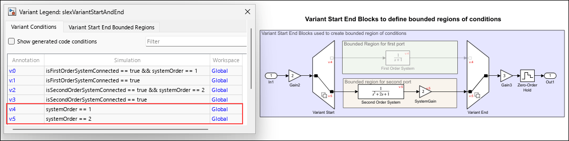
In the first model of this example, the variant conditions on the Variant Start block are set to systemOrder == 1 and systemOrder == 2 for the output ports connected to the first-order and second-order systems, respectively. The variant control variable, systemOrder, is defined and set to 2 in the PostLoadFcn callback of the model. During simulation, the variant conditions systemOrder == 1 and systemOrder == 2 from the Variant Start block propagate to the blocks within the bounded region and make them conditional.
Simulate the model.
sim(model);
During simulation, the variant conditions propagate within the bounded region as follows.
The variant condition
systemOrder == 1applies to the blocks connected to the first port of theVariant Startblock. The variant conditionsystemOrder == 2applies to the blocks connected to the second port of theVariant Startblock.
When
systemOrder == 1evaluates totrue, the first-order system is active.
When
systemOrder == 2evaluates totrue, the second-order system is active.
The
Gain2andGain3blocks are unconditional because theVariant StartandVariant Endblocks prevent the variant condition propagation beyond their boundaries.
To visualize the propagated variant conditions, use the Variant Legend. For more information, see Visualize Propagated Variant Conditions and Bounded Regions in Variant Legend.
Confine Variant Conditions Within a Bounded Region to Prevent Unintended Changes
You can confine the propagation of variant conditions to a set of blocks to prevent unintended changes to other model components by defining a bounded region using Variant Start and Variant End blocks.
In the second model of this example, the variant conditions on the Variant Start1 block are set to systemOrder == 1 and systemOrder == 2 for the output ports connected to the first-order and second-order systems, respectively. The Variant Source and Variant Sink blocks within the bounded region have variant conditions isFirstOrderSystemConnected == true and isSecondOrderSystemConnected == true, respectively. The variant control variables systemOrder, isFirstOrderSystemConnected, and isSecondOrderSystemConnected are defined and set to 2, true, and true, respectively, in the PostLoadFcn callback of the model.
During simulation, the variant conditions propagate within the bounded region as follows.
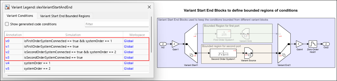
To visualize the propagated variant conditions, use the Variant Legend. For more information, see Visualize Propagated Variant Conditions and Bounded Regions in Variant Legend.
When
isFirstOrderSystemConnected == true && systemOrder == 1evaluates totrue, the first-order system is active.
When
isSecondOrderSystemConnected == true && systemOrder == 2evaluates totrue, the second-order system is active.
The
Gain1andGain4blocks are unconditional because theVariant Start1andVariant End1blocks prevent the variant condition propagation beyond their boundaries.

