Anti-Windup-Regelung mithilfe eines PID Controller-Blocks
Dieses Beispiel zeigt, wie Sie Anti-Windup-Methoden verwenden können, um ein Integrations-Windup bei PID-Reglern zu vermeiden, wenn die Aktoren gesättigt sind. Der Block „PID Controller“ in Simulink® umfasst zwei integrierte Anti-Windup-Methoden, back-calculation und clamping sowie einen Trackingmodus für den Umgang mit komplexeren industriellen Szenarien. Der Block „PID Controller“ unterstützt mehrere Funktionen, die einen Umgang mit Steuerungs-Windup-Problemen in häufig auftretenden industriellen Szenarien ermöglichen.
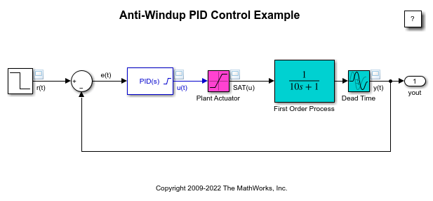
Die zu steuernde Regelstrecke ist ein gesättigter Prozess erster Ordnung mit Totzeit.
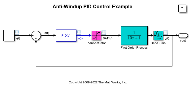
Der Block „PID Controller“ weist Parameter auf, die mit dem Simulink® Control Design™ PID-Tuner mit ignorierter Sättigung abgestimmt wurden.
Die gesteuerte Regelstrecke ist ein Prozess erster Ordnung mit Totzeit, beschrieben durch
 .
.
Die Regelstrecke weist bekannte Eingangssättigungsgrenzen von [-10, 10] auf, die im mit Plant Actuator bezeichneten Saturation-Block berücksichtigt sind. Der Block „PID Controller“ in Simulink umfasst zwei integrierte Anti-Windup-Methoden, wodurch er die verfügbaren Informationen über die Eingangssättigung der Regelstrecke berücksichtigen kann.
Leistung ohne Anti-Windup
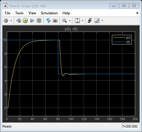
Betrachten Sie zunächst die Auswirkungen der Sättigung auf die geschlossene Schleife, wenn das Sättigungsmodell nicht vom Block „PID Controller“ berücksichtigt wird. Eine Simulation des Modells führt zu diesen Ergebnissen. Die Abbildung zeigt den Sollwert gegenüber der gemessenen Ausgabe ohne Anti-Windup.
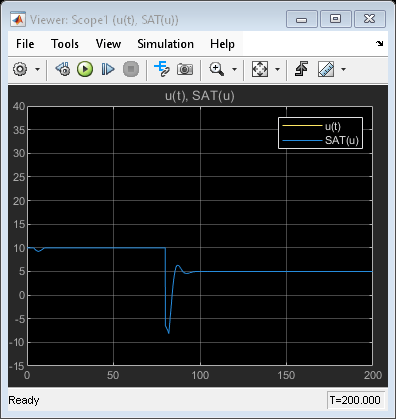
Die Abbildung zeigt die Regler-Ausgabe und den gesättigten Eingang ohne Anti-Windup.

Diese Abbildungen veranschaulichen zwei Probleme bei der Steuerung eines Systems mit Eingangssättigung:
Wenn der Sollwert
10beträgt, erreicht das PID-Steuerungssignal bei etwa36.29einen stabilen Zustand, außerhalb des Bereichs des Aktors. Der Regler arbeitet dementsprechend in einer nichtlinearen Region, in der ein Anstieg des Steuerungssignals keine Auswirkung auf die Systemausgabe hat, eine Bedingung, die als Windup bezeichnet wird. Beachten Sie, dass die DC-Verstärkung der Regelstrecke das Einselement ist. Dementsprechend muss die Steuerungsausgabe keinen stabilen Wert außerhalb des Bereichs des Aktors aufweisen.Bei einem Sollwert von
5besteht eine erhebliche Verzögerung, bevor der PID-Regler in den Aktorbereich zurückkehrt.
Wird der PID-Regler so entworfen, dass er die Auswirkungen einer Sättigung berücksichtigt, verbessert dies die Leistung, da der Regler die meiste Zeit in der linearen Region arbeitet und schnell aus einer Nichtlinearität zurückkehrt. Hierfür können Sie Anti-Windup-Methoden verwenden.
Block basierend auf Rückrechnung für Anti-Windup konfigurieren
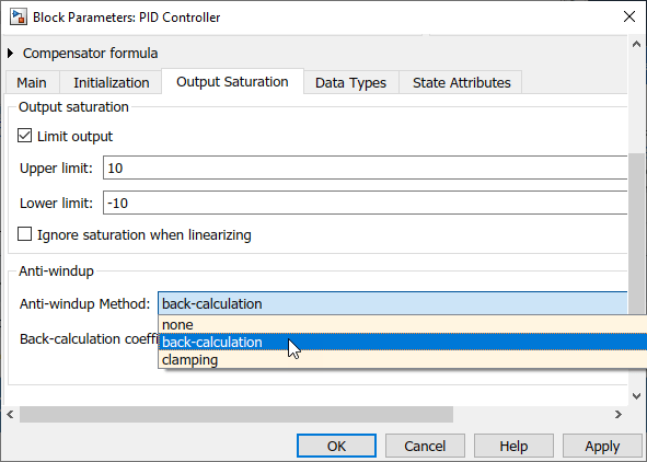
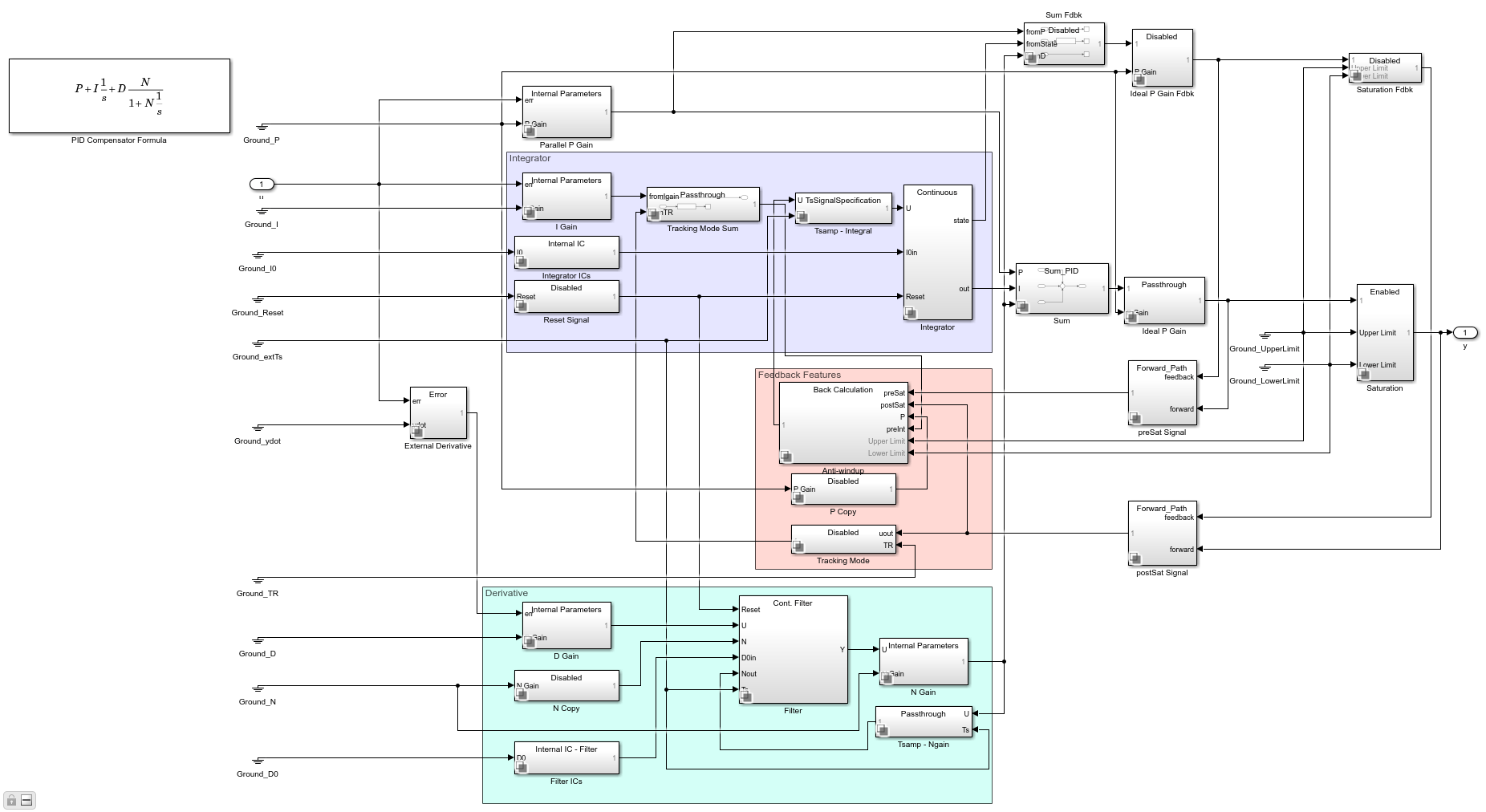
Die Anti-Windup-Methode „Rückrechnung“ verwendet eine Feedbackschleife, um den internen Integrator des Blocks „PID Controller“ „abzuwickeln“, wenn die Steuerung bestimmte Sättigungsgrenzwerte erreicht und in den nichtlinearen Betrieb eintritt. Um Anti-Windup zu aktivieren, rufen Sie die Registerkarte Output Saturation im Blockdialog auf. Wählen Sie Limit output aus und geben Sie die Sättigungsgrenzwerte für die Regelstrecke ein. Wählen Sie daraufhin aus der Liste Anti-windup method die Option back-calculation aus. Geben Sie daraufhin den Back-calculation coefficient (Kb) an. Der Kehrwert dieser Verstärkung ist die Zeitkonstante der Anti-Windup-Schleife. In diesem Beispiel wird die Rückrechnungs-Verstärkung 1 ausgewählt. Weitere Informationen zur Auswahl dieses Werts finden Sie unter [1].
Ist die Rückrechnung aktiviert, verfügt der Block über eine interne Tracking-Schleife, die die Integrator-Ausgabe „abwickelt“. Diese Abbildung zeigt die unmaskierte Ansicht des Blocks „PID Controller“ mit Rückrechnung.
Beachten Sie, wie schnell das PID-Steuersignal in die lineare Region zurückkehrt und wie schnell die Schleife sich von der Sättigung erholt.
Der Steuerungsausgang u(t) und der gesättigte Eingang SAT(u) stimmen überein, da Limit output aktiviert ist.
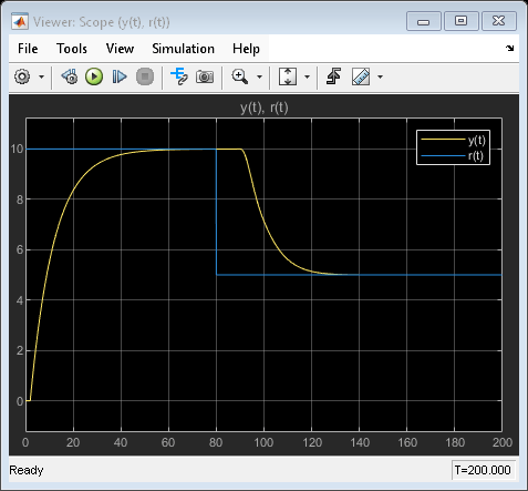
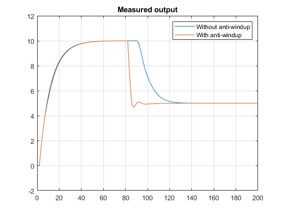
Um die Wirkung von Anti-Windup zu veranschaulichen, zeigt diese Abbildung die gemessene Ausgabe der Regelstrecke y(t) mit und ohne Anti-Windup.
Block basierend auf Integrator Clamping für Anti-Windup konfigurieren
Eine weitere gebräuchliche Anti-Windup-Strategie basiert auf bedingter Integration. Um Anti-Windup zu aktivieren, wählen Sie im Dialogfeld „Block Parameters“ die Registerkarte Saturation aus. Wählen Sie Limit output aus und geben Sie die Sättigungsgrenzwerte für die Regelstrecke ein. Wählen Sie daraufhin aus der Liste Anti-windup method die Option clamping aus.
Diese Abbildung zeigt den Sollwert und die gemessenen Ausgabe mit aktiviertem Clamping.

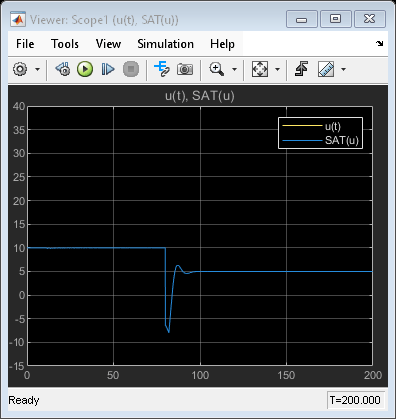
Diese Abbildung zeigt, dass der Steuerungsausgang u(t) und der gesättigte Eingang SAT(u) übereinstimmen, da Limit output aktiviert ist.
Weitere Informationen zur Verwendung von Clamping finden Sie unter [1].
Trackingmodus zum Umgang mit komplexen Anti-Windup-Szenarien verwenden
Die bisher erörterten Anti-Windup-Strategien verlassen sich auf integrierte Methoden zur Verarbeitung der Sättigungsinformationen, die dem Block über seinen Dialog zur Verfügung gestellt werden. Damit diese integrierten Techniken wie beabsichtigt funktionieren können, müssen zwei Bedingungen erfüllt sein:
Die Sättigungsgrenzwerte der Regelstrecke sind bekannt und können in den Blockdialog eingegeben werden.
Das Ausgangssignal des Blocks „PID Controller“ ist das einzige Signal, das zu dem Aktor geleitet wird.
Diese Bedingungen können die Nutzung bei allgemeinen Anti-Windup-Szenarien einschränken. Der Block „PID Controller“ weist einen Trackingmodus auf, mit dem Sie eine Anti-Windup-Schleife mittels Rückrechnung extern einrichten können. Die nächsten beiden Beispiele stellen die Verwendung des Trackingmodus für Anti-Windup-Zwecke dar.
Anti-Windup für gesättigte Aktoren mit kaskadierenden Dynamiken
Anti-Windup für PID-Steuerung mit Feed-Forward
Anti-Windup-Methode für gesättigte Aktoren mit kaskadierenden Dynamiken konstruieren
Der Aktor in sldemo_antiwindupactuator weist komplexe Dynamiken auf. Komplexe Dynamiken treten häufig auf, wenn ein Aktor über eine eigene geschlossene Dynamik verfügt. Der PID-Regler befindet sich in einer äußeren Schleife und sieht die Aktor-Dynamiken als innere Schleife; dies wird auch als kaskadierte gesättigte Dynamik bezeichnet.
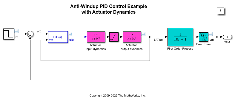
Für eine erfolgreiche Anti-Windup-Strategie muss die Aktor-Ausgabe wieder zum Tracking-Port des Blocks „PID Controller“ geleitet werden. Um den tracking mode des Blocks „PID Controller“ zu konfigurieren, klicken Sie im Blockparameter-Dialogfeld auf die Registerkarte Initialization. Wählen Sie Enable tracking mode aus und geben Sie die Verstärkung Kt an. Der Kehrwert dieser Verstärkung ist die Zeitkonstante der Tracking-Schleife. Weitere Informationen zur Auswahl der Verstärkung finden Sie unter [1].
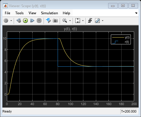
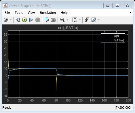
Der gemessene Ausgang der Regelstrecke y(t) und des Steuerungsausgangs u(t) reagieren fast unmittelbar auf Änderungen des Sollwerts. Ohne den Anti-Windup-Mechanismus zeigen sich bei den Reaktionen lange Verzögerungen.
Anti-Windup-Mechanismus für PID-Steuerung mit Feed-Forward
Bei einer weiteren üblichen Steuerungskonfiguration erhält der Aktor ein Steuersignal, bei dem es sich um eine Kombination aus PID-Steuersignal und Feed-Forward-Steuersignal handelt. Öffnen Sie das Modell sldemo_antiwindupfeedforward.
Um eine Anti-Windup-Schleife zur Rückberechnung präzise zu erstellen, sollte das Trackingsignal den Beitrag des Feed-Forward-Signals abziehen. So kann der Block „PID Controller“ seinen Anteil des effektiven Steuersignals, das am Aktor anliegt, ermitteln.
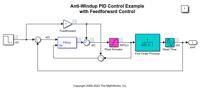
Die Feed-Forward-Verstärkung ist hier die Einseinheit, da die Regelstrecke eine DC-Verstärkung von 1 aufweist.
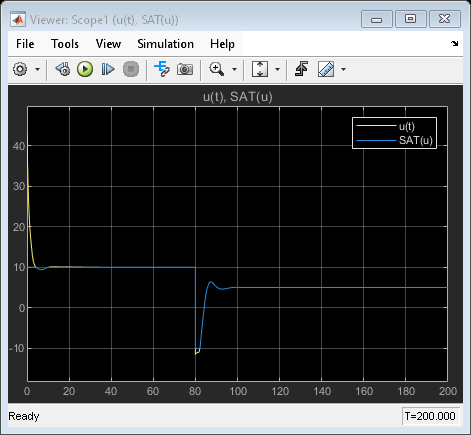
Der gemessene Ausgang der Regelstrecke y(t) und des Steuerungsausgangs u(t) reagieren fast unmittelbar auf Änderungen des Sollwerts. Beachten Sie, wie bei einem Sollwert von 10 die Steuerungsausgabe u(t) absinkt, um in den Bereich des Aktors zu gelangen.
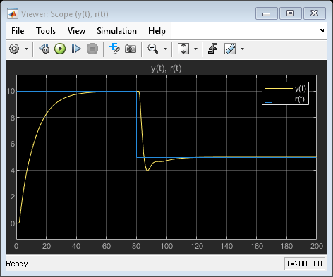
Beachten Sie, wie bei einem Sollwert von 10 die Steuerungsausgabe u(t) absinkt, um in den Bereich des Aktors zu gelangen.
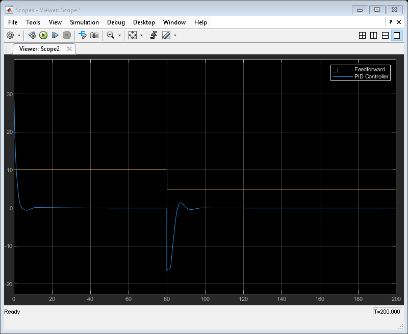
Diese Abbildung zeigt den PID-Regler-Ausgang und Feed-Forward-Eingang mit Anti-Windup.
Referenzen
[1] Åström, Karl J., and Tore Hägglund. Advanced PID Control. Triangle Park, NC: International Society of Automation, 2006.