Quadrature Encoder
R2026bMeasure rotation of encoder in ticks
Quadrature Encoder block
To add a block to a model, double-click the canvas and start typing the block name. Then, select the block from the list.
Libraries:
Simulink Coder Support Package for NXP FRDM-K64F Board
Description
Add-On Required: This feature requires the Simulink Coder Support Package for NXP FRDM-K64F Board add-on.
The Quadrature Encoder block reads the rotation tick count and the direction of the encoder to which the board is connected.
When you rotate the encoder in a clockwise direction, the tick count increases. When you rotate the encoder in a counterclockwise direction, the tick count decreases.
Using the parameters of this block, specify the encoding mode, reset mode, and phase polarity.
On the board, the Flexible Timer Module (FTM) peripheral provides dedicated pins for the Phase A and Phase B output signals from the encoder.
Connect the Phase A output pin on the encoder to the PTB18 pin on the board. Connect the Phase B output pin on the encoder to the PTB19 pin on the board.
Ports
Input
Output
Parameters
You can select encoding mode to calculate the rotation tick count.
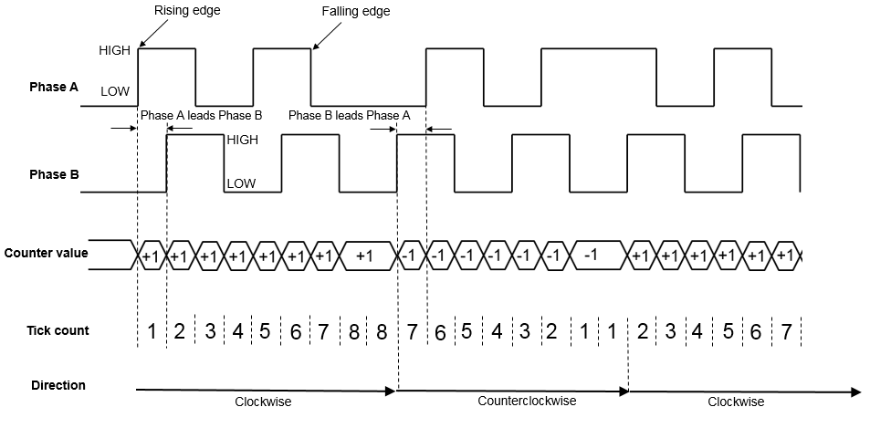
Quadrature– The board performs X4 encoding measurement on the encoder. In this type of encoding, each rising and falling edges of the Phase A and the Phase B signals are counted.When the Phase A leads the Phase B signal (encoder in clockwise direction), the tick count increases for each rising/falling edge of both of the signals. When the Phase A lags behind the Phase B signal (encoder in counterclockwise direction), the tick count decreases for each rising/falling edge of both of the signals.
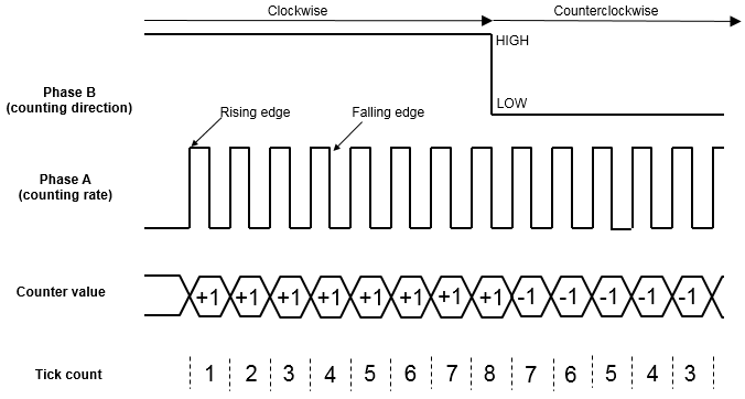
Count and Direction– The Phase A signal controls the counting rate. The Phase B signal controls the counting direction. For example, when the Phase B signal is HIGH (encoder in clockwise direction), the tick count increases for every rising edge of the Phase A signal. When the Phase B signal is LOW (encoder in counterclockwise direction), the tick count decreases for every rising edge of the Phase A signal.
When you select this parameter, the Dir port
becomes available.
When the encoder rotates in a clockwise direction, the port outputs 1. When the encoder rotates in a counterclockwise direction, the port outputs 0.
This block supports three different reset modes. The reset modes are described in the example table.
Consider that the encoder wheel, connected to the board, has 90 slots. This means that, the encoder tick count is one for every 4 degrees of rotation.
Assume that the block sample time is 1 second, and the tick count at time instant T = 0 is 0.
No reset– The encoder reading is not reset and the block outputs the total ticks of rotation.For example, in the table, between T = 0 and T = 1, the encoder rotates 20 degrees in a clockwise direction. Therefore, the tick count is 5.
Between T = 1 and T = 2, the encoder rotates 40 degrees in a clockwise direction, and therefore, the tick count is 15 at T = 2 (5 from T = 1 and 10 from T = 2).
In this mode, the output at any time instant is a cumulative sum of the previous count and the current count.
Reset at each sample time– For each sample period, the block outputs the encoder reading, and then resets it to 0.For example, in the table, between T = 0 and T = 1, the encoder rotates 20 degrees in a clockwise direction. Therefore, the tick count is 5.
Between T = 1 and T = 2, the encoder rotates 40 degrees in a clockwise direction, and therefore, the tick count is 10.
In this mode, the output is the tick count at a given sample time.
Reset by external signal– When you set the Reset mode parameter toReset by external signal, an input port becomes available.For each sample period, the block outputs the encoder reading since the last reset. The encoder reading is reset to 0 based on the input value at this port. When you send a value other than 0 to the block input, the block resets the encoder reading to 0.
For example, in the table, between T = 0 and T = 1, the encoder rotates 20 degrees in a clockwise direction. Therefore, the tick count is 5 at T=1.
Between T = 1 and T = 2, the encoder rotates 40 degrees in a clockwise direction. Therefore, the tick count is 15 at T = 2 (5 from T = 1 and 10 from T = 2).
Between T = 2 and T = 3, the encoder rotates 60 degrees in a clockwise direction. Therefore, the tick count is 30 at T = 3 (15 from T = 2 and 15 from T = 3). As the block input value is a nonzero value at T=3, the block resets the encoder reading to 0.
Between T = 3 and T = 4, the encoder rotates 20 degrees in a counterclockwise direction. Therefore, the tick count is -5 at T = 4 (0 from T = 3 and -5 from T = 4).
In this mode, when the external signal is 0, the output is calculated the same as in the
No resetmode. When the external signal is nonzero, the output is calculated the same as in theReset at each sample timemode.

When you select this check box, the block inverts the Phase A signal before identifying it for the rising and falling edges. Depending on the encoder that you use, you can choose to invert the polarity.
When you select this check box, the block inverts the Phase B signal before identifying it for the rising and falling edges. Depending on the encoder that you use, you can choose to invert the polarity.
Specify how often this block reads the rotation, in seconds.
Dependencies
This parameter appears only when you set the Reset
mode parameter to No reset or Reset
at each sample time.
Version History
Introduced in R2017a

