Validate Controller with HIL Testing for LLC Resonant Converter
R2026bIn this step of the LLC Resonant Converter Controller Design Workflow example, you validate the LLC resonant converter controller using model-in-the-loop (MIL) and hardware-in-the-loop (HIL) simulation before energizing a physical converter. To get started, open the project and click the HIL Workflow shortcut on the project toolstrip. The shortcut opens this live script so you can step through it top to bottom.
Overview
This reference example demonstrates a workflow for testing a DC/DC resonant LLC converter controller using both Model-in-the-Loop (MIL) and Hardware-in-the-Loop (HIL) methods. The controller runs on a Texas Instruments® C2000™ Delfino™ F28379D LaunchPad™ development kit, and the LLC converter plant runs on a Speedgoat® real-time target machine with an IO334 FPGA I/O module.
The workflow lets you validate the compensator without energizing a physical converter. You compare the controller against a detailed switching plant on the desktop, promote the plant to the FPGA, and finally close the loop with the deployed C2000 controller against the FPGA plant so faults, load steps, and set-point changes can be exercised without damaging hardware.
System Requirements
The system requirements can differ based on the chosen simulation mode. The lists below cover the requirements for conducting controller HIL testing.
MathWorks® Products
Simulink® Real-Time™
Simscape™ Electrical™
Embedded Coder®
C2000™ Microcontroller Blockset
Motor Control Blockset
Speedgoat Products
Third-Party Products
Supported Model-Based Design Use Cases
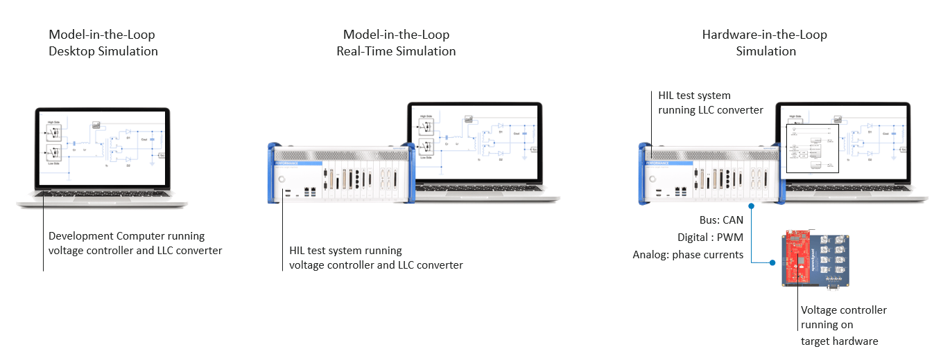
This example supports the following simulation modes (see image below):
Desktop MIL: Both the DC/DC converter plant and controller run on the development computer. The converter is modeled using detailed MOSFET switches. This plant model is hereafter referred to as golden reference for this topology. Use this simulation mode as baseline for future testing.
Real-time MIL: Both the DC/DC converter plant and voltage controller run in real-time on a Speedgoat HIL test system. The DC/DC converter plant executes on a Simulink®-Programmable FPGA I/O. The converter is controlled by firing pulses produced by a PWM generator. This plant version provides the required resolution and fidelity for simulating high frequency switching dynamics. Use this mode to validate real-time aspects of both plant and controller. The development computer is used to control the real-time simulation, fine-tune controller, and measure real-time signals directly out of Simulink®.
HIL: Interface DC/DC controller running on intended target hardware with the DC/DC converter model running on the Speedgoat HIL test system. Use this mode to perform interactive and automated HIL testing of your embedded controller.
Workflow
A. Run Desktop Simulation and Fine Tune Controller Parameters
To create a "golden reference" for every later comparison, first run the detailed switching model on the desktop. This model uses Simscape(TM) Electrical(TM) MOSFET switches, which represent the converter dynamics with the highest fidelity available in this workflow. The FPGA and HIL runs are judged against it. Running the model on the desktop also lets you sweep controller parameters programmatically before the physical hardware is in the loop.
Configure the testbench in variant 1 (desktop MIL), set
Vref,
closedLoop, and
enablePWM to the values you want to characterize, then start the simulation. The resulting
Vout and
I signals are logged to Simulation Data Inspector and renamed so subsequent runs can be compared against them.
mdl = 'ResonantLLCConverterCHILSystem';
open_system(mdl);
open(Simulink.BlockPath('ResonantLLCConverterCHILSystem/User Interface'));

%Load parameters
resonantllcconverterhildata;


% Configure testbench for desktop MIL simulation
set_param([bdroot '/LLC Resonant Converter System/simulationVariant'], 'Value','1');

%Use a set of parameters for tuning
set_param([bdroot '/LLC Resonant Converter System/Vref'], 'Value','35');
set_param([bdroot '/LLC Resonant Converter System/closedLoop'], 'Value','1');
set_param([bdroot '/LLC Resonant Converter System/enablePWM'], 'Value','1');


% Start dekstop simulation
set_param(mdl,'SimulationCommand','Start','StopTime','2.5e-2');
simOut = sim('ResonantLLCConverterCHILSystem.slx','SimulationMode','normal');

% Get the most recently created Simulation Data Inspector run
experimentRunMIL = Simulink.sdi.Run.getLatest;
experimentRunMIL.Name = ['ControllerTuningMIL - ' char(experimentRunMIL.DateCreated)];
VMIL = getSignalsByName(experimentRunMIL,'Vout');
IMIL = getSignalsByName(experimentRunMIL,'I');

Simulink.sdi.setSubPlotLayout(2,1);
plotOnSubPlot(VMIL,1,1,true);
plotOnSubPlot(IMIL,2,1,true);
Simulink.sdi.view;
B. Build and Validate DC/DC Converter Model
B1. Generate Ready-to-Run FPGA Example from Resonant Converter Template
To move the converter plant onto the Speedgoat FPGA, generate an FPGA bitstream from the Motion Control HDL I/O template and drop the resulting block into the model. This example ships with a fixed bitstream so you can start experimenting immediately, but the template is the recommended starting point when your converter parameters differ from the shipped defaults. Regenerating the bitstream keeps the FPGA model consistent with the desktop plant used for the golden reference.
The present reference example contains a fixed bitstream that will program the IO334 FPGA to simulate a resonant converter for HIL testing. It is a good way to start experimenting with HIL setups and can serve as an example of architecture for your projects. To deploy your own models, you can use the LLC Resonant Converter template from the Speedgoat - Motion Control HDL I/O Blockset: the basic template includes a similar plant as the one used in this example, but where many plant parameters such as characteristics of circuit elements can be modified before generating.
Once you have generated the bitstream using the script or the HDL workflow advisor, simply replace the block in the subsystem with the block in the generated model ( gm_L_slrt.slx).
mdl = 'ResonantLLCConverterCHILSystem';
open_system(mdl);
open(Simulink.BlockPath('ResonantLLCConverterCHILSystem/LLC Resonant Converter System/HDL Subsystem/Real-Time'));
You also need to add your bitstream (*.mcs file generated from running HDL Workflow Advisor on the template) to the project. For example, you can place it in the SupportFiles/Bitstream folder and add the file to the Simulink® Project.
B2. Validate Real-Time Resonant Converter Model
To confirm the FPGA plant behaves like the desktop reference before you close the loop with real controller hardware, run the model in variant 2 (real-time MIL) and overlay the response on the golden reference from Step A. Reusing the same
Vref,
closedLoop, and
enablePWM settings ensures the two runs are directly comparable. Small differences are expected because the FPGA plant uses a fixed-step simulation and simplified switch models, but large deviations point to model or scaling issues that must be resolved before HIL testing.
mdl = 'ResonantLLCConverterCHILSystem';
open_system(mdl);
open(Simulink.BlockPath('ResonantLLCConverterCHILSystem/User Interface'));

% Configure testbench for Real-time Model in the loop
set_param([bdroot '/LLC Resonant Converter System/simulationVariant'], 'Value','2');

%Use the same set of parameters for tuning
set_param([bdroot '/LLC Resonant Converter System/Vref'], 'Value','35');
set_param([bdroot '/LLC Resonant Converter System/closedLoop'], 'Value','1');
set_param([bdroot '/LLC Resonant Converter System/enablePWM'], 'Value','1');

% Build the Simulink model
slbuild(mdl);

% Create and connect to the Speedgoat real-time target machine
tg = slrealtime;
tg.connect;

% Download and install the real-time example on the target machine
tg.load(mdl);

% Start simulation of real-time example
tg.setStopTime(2.5e-2);
tg.start;
pause(10);

% Get the most recently created Simulation Data Inspector run
experimentRunRT = Simulink.sdi.Run.getLatest;
experimentRunRT.Name = ['RealTimeMIL - ' char(experimentRunRT.DateCreated)];
VRT = getSignalsByName(experimentRunRT,'Vout');
IRT = getSignalsByName(experimentRunRT,'I');

% Plot the voltage and currents from the Simscape switching converter
% against the real time converter.
Simulink.sdi.setSubPlotLayout(2,1);
plotOnSubPlot(VRT,1,1,true);
plotOnSubPlot(IRT,2,1,true);
Simulink.sdi.view;
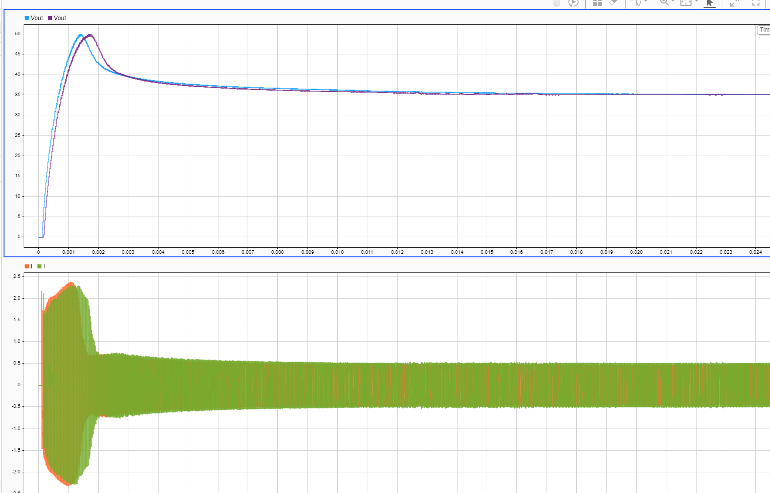
With both runs recorded in the Simulation Data Inspector, overlay the desktop and real-time
Vout and
I signals to confirm the FPGA plant tracks the golden reference in both steady-state and transient regions. Small deviations are expected because the FPGA plant discretizes the switching dynamics at a fixed step; larger mismatches usually indicate that the bitstream parameters do not match
resonantllcconverterhildata.m, and the FPGA model needs to be regenerated with corrected values before proceeding.
C. Configure Testbench for HIL Simulation
C1. Generate Code and Deploy Controller Logic to Target Hardware
To move the compensator from simulation onto production-grade hardware, generate C code from
ResonantLLCcontrollerF28379d and deploy it to the F28379D LaunchPad(TM). Embedded Coder(R) emits the initialize and step functions using the same fixed-point representation the C2000(TM) Microcontroller Blockset expects, so the code that runs on the target is bit-identical to the model that produced the golden reference. Any post-deployment behavior change now points to an I/O, timing, or scaling issue rather than a controller redesign.
% Open model containing controller logic for F28379D target hardware
mdl = 'ResonantLLCcontrollerF28379d';
open_system(mdl);

% Connect target hardware to host computer (USB)
% Build and Deploy Code to target hardware
slbuild(mdl);
C2. Connect Target Hardware to HIL Test System
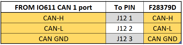
To close the physical loop between the controller and the FPGA plant, wire the F28379D LaunchPad(TM) to the Speedgoat IO334 and IO611 modules according to the tables below. The IO3xx-21 expansion card carries the PWM outputs and analog feedback that the controller expects, while the IO611 CAN link carries the set-point and telemetry traffic exchanged with the Simulink(R) host. A single mis-wired pin is enough to make the HIL run diverge from the golden reference, so verify the mapping before energizing the setup.
The following table provides a detailed pin mapping between the F28379D LaunchPad(TM), Speedgoat IO334 Simulink(R)-Programmable FPGA I/O Module and Speedgoat CAN I/O Module.
First the IO3xx-21 expansion card should be connected to a terminal board and the following connection between the terminal board and the F28379D LaunchPad™ made :

Then using the IO334 I/O Box, the following connection must be realized :

Finally, connect the Speedgoat IO611 CAN port to the F28379D LaunchPad™ pins.
D. Controller Hardware-in-the-Loop Testing
D1. Perform Interactive Testing using Simulink**(R)** Dashboard
To validate the deployed controller against faults you cannot safely apply on a real converter (for example, a device short), configure the testbench in variant 3 (HIL over CAN) and trigger faults from the Simulink(R) dashboard. Running
Open_Ap for a bounded window and returning it to the default value keeps the FPGA plant, the controller, and the CAN link in a known state at the end of the test, so consecutive fault scenarios can be executed without restarting the target.
mdl = 'ResonantLLCConverterCHILSystem';
tg = slrealtime;
open_system(mdl);

% Configure testbench for HIL simulation using CAN
% interface (use 1 for Real-time model)
set_param([bdroot '/LLC Resonant Converter System/simulationVariant'], 'Value','3')

set_param([bdroot '/LLC Resonant Converter System/Vref'], 'Value','35')

% Build the Simulink model
slbuild(mdl);

% Download and install the real-time example on the target machine
tg.load(mdl);
tg.setStopTime(inf);

% Start simulation of real-time example
tg.start;
pause(5)
set_param([bdroot '/LLC Resonant Converter System/Fault Trigering/Open_Ap'], 'Value','1')
pause(5)
tg.stop
%Switch back to default configuration
set_param([bdroot '/LLC Resonant Converter System/Fault Trigering/Open_Ap'], 'Value','0')
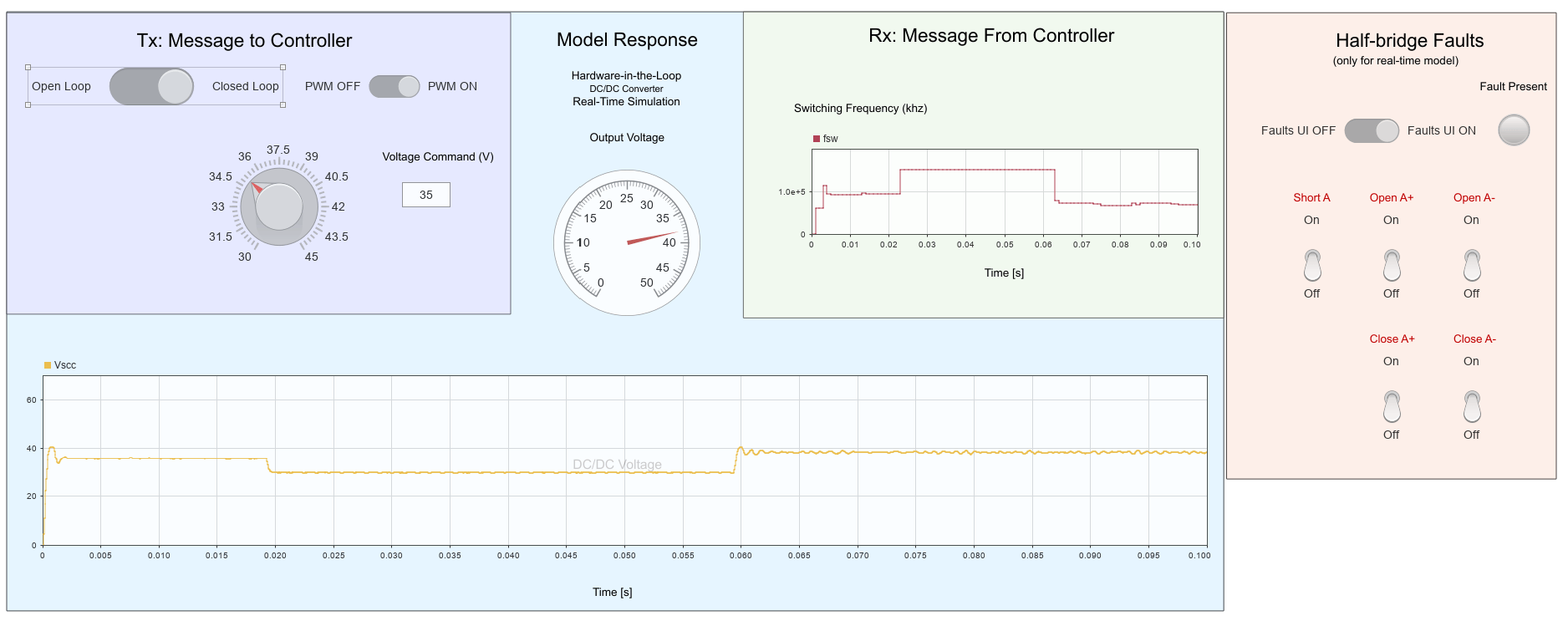
Open the Simulink® user interface and activate the 'Faults UI' option. This lets you
toggle various faults on and off to assess the controller's response.
See Also
Topics
- Configure and Simulate LLC Resonant Converter Controller
- Estimate Online Frequency Response of LLC Resonant Converter
- Verify Stability Margins and Analyze Sensitivity for LLC Resonant Converter
- Validate Controller Gains with Frequency Response Estimation on Hardware
- Export Controller Algorithm Custom Targets

