Design of Experiments Overview
R2026bAs powertrain systems increase in complexity, efficient experimental design becomes essential. Traditional full-factorial testing becomes impractical as the number of variables increases, often leading to test times that are not feasible. You can use the Design Experiment tool in the Model-Based Calibration Toolbox™ to address this challenge by selecting test points that provide the highest value, reducing time spent testing hardware while still producing accurate models. The Model-Based Calibration Toolbox supports systematic test design planning and offers prebuilt designs that you can customize. For more information, see Design of Experiments.
You can start most experiments with a one‑stage design, which generates a complete set of test points to run in a single step. Use a one-stage design by default. This approach generates a space‑filling design, fits a Gaussian process response model, and applies a convex hull boundary, making it suitable for most experimental designs and operating regions.
After generating the design, execute the test points on physical hardware or export them to a Simulink® model to collect data through simulation. Once data collection is complete, proceed to Data Preparation to import and clean the data for model fitting. For more complex testing scenarios, see What Models Are Available? to learn about alternative design options.
If you have already collected data, start with the Data Preparation stage of the Model-Based Calibration optimization workflow. See Data Preparation Overview.
Choose Design Approach and Define Inputs
Start by defining the structure of the experiment, including which inputs are varied and how operating points are distributed across the design space. You can adjust the number of inputs and define symbols, minimum and maximum values, signal names, and any required transformations.
In the Design Experiment tool, choose a test plan type and define the design inputs. This step focuses on one-stage designs, which are suitable for most experimental scenarios. For workflows that require staged data collection or hierarchical input structures, see Fit a Two-Stage Model or Fit a Point-by-Point Model.
Use the Design Editor in the MBC Model Fitting app to specify controllable inputs, operating ranges, constraints, and the design type appropriate for your application. Based on these settings, the tool generates test points that provide space-filling coverage within the feasible operating region. By default, the app uses a Gaussian process model (GPM) as the response model because the GPM typically provides good fits across a wide range of experiments without extensive tuning. The boundary of the input space is modeled using a convex hull, so the design conforms to the feasible operating region.
Use test plan templates to select a design strategy appropriate for your system behavior and data collection constraints.
| Test Plan Template | Description | More Info |
|---|---|---|
| One-Stage | The one-stage design fits all data in a single process and can provide predictions between operating points. Use a one-stage design when your system behavior is stable, you can plan all runs up front, and the input data does not have a hierarchical structure. When you set up your model inputs, you can:
|
Define Design Constraints
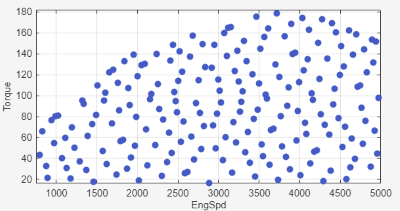
Not all combinations of input values can be tested on physical hardware. For example, operating an engine at high torque below its idle speed is not feasible. Define design constraints to prevent the experimental design from including such points by limiting the design space to the feasible operating region and realistic calibration settings for the system.
| Constraint Option | Example | More Info |
|---|---|---|
| This example shows a space‑filling design constrained by a one‑dimensional maximum torque boundary.
| For more constraint options, see Define Design Constraints. |
Generate Design
Select the design type to define how you place the operating points within the test structure you have chosen.
| Design Type | Use Case | Example | More Info |
|---|---|---|---|
| Space‑filling designs |
|
| |
| Optimal designs |
|
| Create an Optimal Design |
| Classical designs |
|
| Create a Classical Design |
After generating a design, expand it with additional points and visually compare designs to verify coverage, point distribution, and boundary behavior before executing the experiment.

