Detect Vehicles in Lidar Using Image Labels
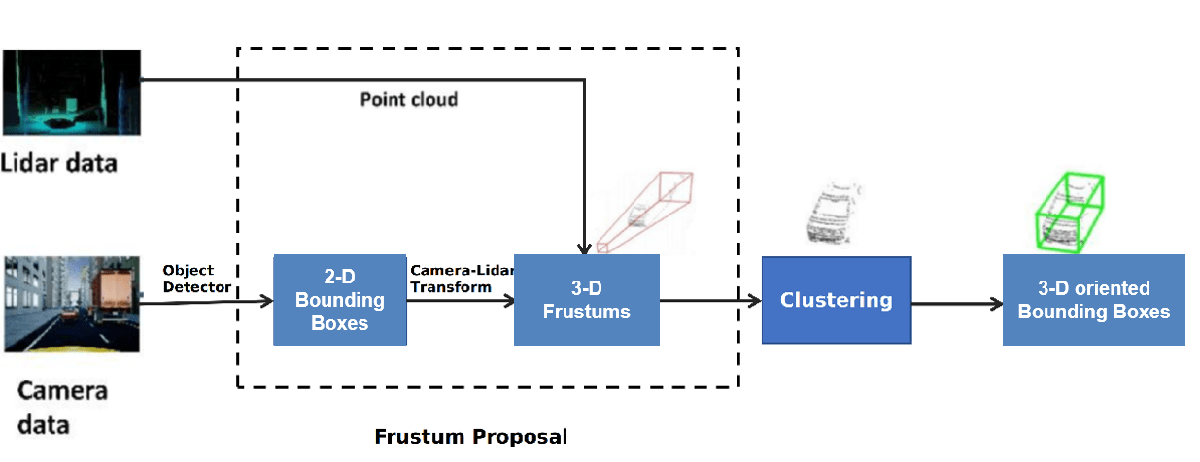
This example shows you how to detect vehicles in lidar using label data from a co-located camera with known lidar-to-camera calibration parameters. Use this workflow in MATLAB® to estimate 3-D oriented bounding boxes in lidar based on 2-D bounding boxes in the corresponding image. You will also see how to automatically generate ground truth as a distance for 2-D bounding boxes in a camera image using lidar data. This figure provides an overview of the process.
Load Data
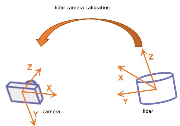
This example uses lidar data collected on a highway from an Ouster OS1 lidar sensor and image data from a front-facing camera mounted on the ego vehicle. The lidar and camera data are approximately time-synced and calibrated to estimate their intrinsic and extrinsic parameters. For more information on lidar camera calibration, see Lidar and Camera Calibration.
Use the helperDownloadWPIData helper function, attached to this example as a supporting file, to download the data.
[imageDataLocation, lidarDataLocation] = helperDownloadWPIData();
Note: The download time for the data depends on the speed of your internet connection. During the execution of this code block, MATLAB is temporarily unresponsive.
Alternatively, you can use your web browser to first download the datasets to your local disk, and then uncompress the files.
Load the data into the workspace.
% Load downloaded images data into the workspace
images = imageSet(imageDataLocation);
imageFileNames = images.ImageLocation;

% Load downloaded lidar data into the workspace
load(lidarDataLocation);

% Load calibration data
if ~exist('calib','var')
    load('calib.mat')
end

% Define camera to lidar transformation matrix
camToLidar = calib.extrinsics;
intrinsics = calib.intrinsics;
This example uses prelabeled data to serve as ground truth for the 2-D detections from the camera images. These 2-D detections can be generated using deep learning-based object detectors like vehicleDetectorYOLOv2 (Automated Driving Toolbox), vehicleDetectorFasterRCNN (Automated Driving Toolbox), and vehicleDetectorACF (Automated Driving Toolbox). For this example, the 2-D detections have been generated using the Training Image Labeler app. These 2-D bounding boxes are vectors of the form: , where represent the xy-coordinates of the top-left corner, and represent the width and height of the bounding box respectively.
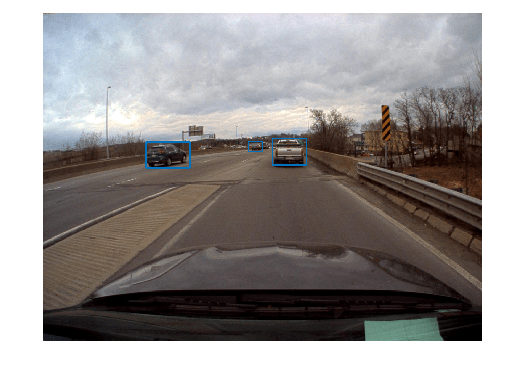
Read a image frame into the workspace, and display it with the bounding boxes overlaid.
load imageGTruth.mat
im = imread(imageFileNames{50});
imBbox = imageGTruth{50};

figure
imshow(im)
showShape('rectangle',imBbox)
3-D Region Proposal
To generate cuboid bounding boxes in lidar from the 2-D rectangular bounding boxes in the image data, a 3-D region is proposed to reduce the search space for bounding box estimation. The corners of each 2-D rectangular bounding box in the image are transformed into 3-D lines using camera intrinsic parameters and camera-to-lidar extrinsic parameters. These 3-D lines form frustum flaring out from the associated 2-D bounding box in the opposite direction of the ego vehicle. The lidar points that fall inside this region are segmented into various clusters based on Euclidean distance. The clusters are fitted with 3-D oriented bounding boxes, and the best cluster is estimated based on the size of these clusters. Estimate the 3-D oriented bounding boxes in a lidar point cloud, based on the 2-D bounding boxes in a camera image, by using the bboxCameraToLidar function. This figure shows how 2-D and 3-D bounding boxes relate to each other.

The 3-D cuboids are represented as vectors of the form:, where represent the centroid coordinates of the cuboid. represent the length of the cuboid along the x-, y-, and z-axes, and represent the rotation ,in degrees, of the cuboid along the x-, y-, and z-axes.
Use ground truth of the image to estimate a 3-D bounding box in the lidar point cloud.
pc = lidarData{50};

% Crop point cloud to process only front region
roi = [0 70 -15 15 -3 8];
ind = findPointsInROI(pc,roi);
pc = select(pc,ind);

lidarBbox = bboxCameraToLidar(imBbox,pc,intrinsics, ...
    camToLidar,'ClusterThreshold',2,'MaxDetectionRange',[1,70]);
figure
pcshow(pc.Location,pc.Location(:,3))
showShape('Cuboid',lidarBbox)
view([-2.90 71.59])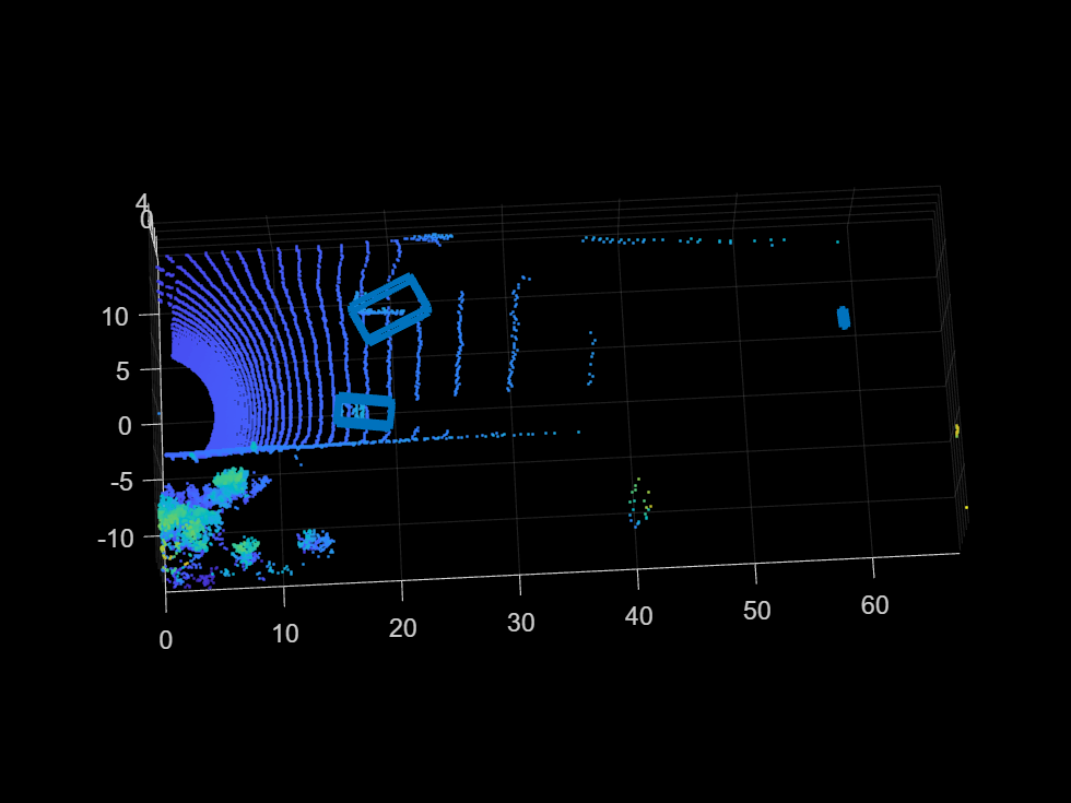
To improve the detected bounding boxes, preprocess the point cloud by removing the ground plane.
Set Up Display
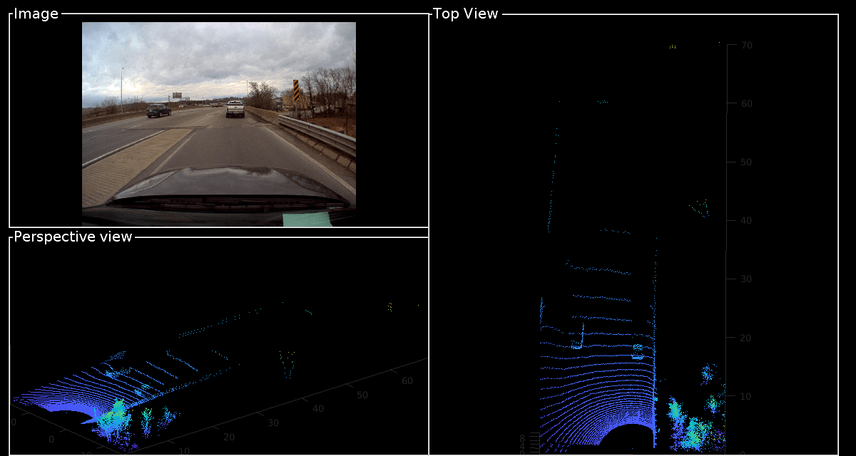
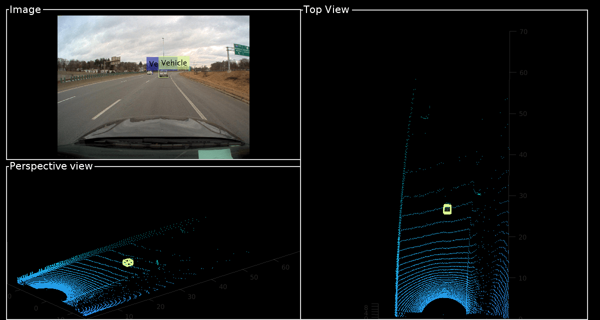
Use the helperLidarCameraObjectsDisplay class to visualize the lidar and image data. This visualization provides the capability to view the point cloud, image, 3-D bounding boxes on the point cloud, and 2-D bounding boxes on the image simultaneously. The visualization layout is consists of these windows:
Image — Visualize an image and associated 2-D bounding boxes
Perspective View — Visualize the point cloud and associated 3-D bounding boxes in a perspective view
Top View — Visualize the point cloud and associated 3-D bounding boxes from the top view
% Initialize display
display = helperLidarCameraObjectsDisplay;
initializeDisplay(display)

% Update display with point cloud and image
updateDisplay(display, im, pc)
Loop Through Data
Run bboxCameraToLidar on 2-D labels over first 200 frames to generate 3-D cuboids
for i = 1:200
    % Load point cloud and image
    im = imread(imageFileNames{i});
    pc = lidarData{i};

    % Load image ground truth
    imBbox = imageGTruth{i};

    % Remove ground plane
    groundPtsIndex = segmentGroundFromLidarData(pc,'ElevationAngleDelta',15, ...
        'InitialElevationAngle',10);
    nonGroundPts = select(pc,~groundPtsIndex);

    if imBbox
        [lidarBbox,~,boxUsed] = bboxCameraToLidar(imBbox,nonGroundPts,intrinsics, ...
            camToLidar,'ClusterThreshold',2,'MaxDetectionRange',[1, 70]);
        % Display image with bounding boxes
        im = updateImage(display,im,imBbox);
    end
    % Display point cloud with bounding box
    updateDisplay(display,im,pc);
    updateLidarBbox(display,lidarBbox,boxUsed)
    drawnow
end
Detected bounding boxes by using bounding box tracking, such as joint probabilistic data association (JPDA). For more information, see Track Vehicles Using Lidar: From Point Cloud to Track List.
Estimate the Distance of Vehicles from the Ego Vehicle
For vehicle safety features such as forward collision warning, accurate measurement of the distance between the ego vehicle and other objects is crucial. A lidar sensor provides the accurate distance of objects from the ego vehicle in 3-D, and it can also be used to create ground truth automatically from 2-D image bounding boxes. To generate ground truth for 2-D bounding boxes, use the projectLidarPointsOnImage function to project the points inside the 3-D bounding boxes onto the image. The projected points are associated with 2-D bounding boxes by finding the bounding box with the minimum Euclidean distance from the projected 3-D points. Since the projected points are from lidar to camera, use the inverse of camera-to-lidar extrinsic parameters. This figure illustrates the transformation from lidar to camera.
% Initialize display
display = helperLidarCameraObjectsDisplay;
initializeDisplay(display)

% Get lidar to camera matrix
lidarToCam = invert(camToLidar);

% Loop first 200 frames. To loop all frames, replace 200 with numel(imageGTruth)
for i = 1:200
    im = imread(imageFileNames{i});
    pc = lidarData{i};
    imBbox = imageGTruth{i};

    % Remove ground plane
    groundPtsIndex = segmentGroundFromLidarData(pc,'ElevationAngleDelta',15, ...
        'InitialElevationAngle',10);
    nonGroundPts = select(pc,~groundPtsIndex);

    if imBbox
        [lidarBbox,~,boxUsed] = bboxCameraToLidar(imBbox,nonGroundPts,intrinsics, ...
            camToLidar,'ClusterThreshold',2,'MaxDetectionRange',[1, 70]);
        [distance,nearestRect,idx] = helperComputeDistance(imBbox,nonGroundPts,lidarBbox, ...
            intrinsics,lidarToCam);

        % Update image with bounding boxes
        im = updateImage(display,im,nearestRect,distance);
        updateLidarBbox(display,lidarBbox)
    end

    % Update display
    updateDisplay(display,im,pc)
    drawnow
end

Supporting Files
helperComputeDistance
function [distance, nearestRect, index] = helperComputeDistance(imBbox, pc, lidarBbox, intrinsic, lidarToCam)
% helperComputeDistance estimates the distance of 2-D bounding box in a given
% image using 3-D bounding boxes from lidar. It also calculates
% association between 2-D and 3-D bounding boxes

%   Copyright 2020 MathWorks, Inc.

numLidarDetections = size(lidarBbox,1);

nearestRect = zeros(0,4);
distance = zeros(1,numLidarDetections);
index = zeros(0,1);

for i = 1:numLidarDetections
    bboxCuboid = lidarBbox(i,:);

    % Create cuboidModel
    model = cuboidModel(bboxCuboid);

    % Find points inside cuboid
    ind = findPointsInModel(model,pc);
    pts = select(pc,ind);

    % Project cuboid points to image
    imPts = projectLidarPointsOnImage(pts,intrinsic,lidarToCam);

    % Find 2-D rectangle corresponding to 3-D bounding box
    [nearestRect(i,:),idx] = findNearestRectangle(imPts,imBbox);
    index(end+1) = idx;
    % Find the distance of the 2-D rectangle
    distance(i) = min(pts.Location(:,1));
end
end

function [nearestRect,idx] = findNearestRectangle(imPts,imBbox)
numBbox = size(imBbox,1);
ratio = zeros(numBbox,1);

% Iterate over all the rectangles
for i = 1:numBbox
    bbox = imBbox(i,:);
    corners = getCornersFromBbox(bbox);

    % Find overlapping ratio of the projected points and the rectangle
    idx = (imPts(:,1) > corners(1,1)) & (imPts(:,1) < corners(2,1)) & ...
        (imPts(:,2) > corners(1,2)) & (imPts(:,2) < corners(3,1));
    ratio(i) = sum(idx);
end

% Get nearest rectangle
[~,idx] = max(ratio);
nearestRect = imBbox(idx,:);
end

function cornersCamera = getCornersFromBbox(bbox)
cornersCamera = zeros(4,2);
cornersCamera(1,1:2) = bbox(1:2);
cornersCamera(2,1:2) = bbox(1:2) + [bbox(3),0];
cornersCamera(3,1:2) = bbox(1:2) + bbox(3:4);
cornersCamera(4,1:2) = bbox(1:2) + [0,bbox(4)];
end
You can also select a web site from the following list:
Americas
- América Latina (Español)
- Canada (English)
- United States (English)
Europe
- Belgium (English)
- Denmark (English)
- Deutschland (Deutsch)
- España (Español)
- Finland (English)
- France (Français)
- Ireland (English)
- Italia (Italiano)
- Luxembourg (English)
- Netherlands (English)
- Norway (English)
- Österreich (Deutsch)
- Portugal (English)
- Sweden (English)
- Switzerland
- United Kingdom (English)