Injection Molding Actuation System
This example shows an injection molding actuation system. The model contains a set of cartridge valves that control pumps, motors, and cylinders to execute the steps of an injection molding process.
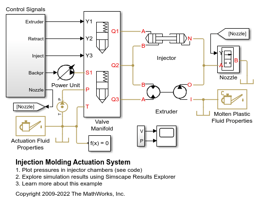
Model
System Schematic
This example uses the molding injection unit actuation system from Vickers Industrial Hydraulics Manual (second edition, 1989). This schematic shows the unit.
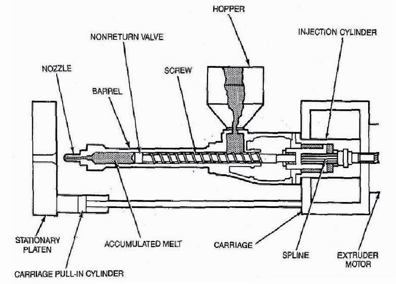
Figure 1. Working Members of the Molding Machine Injection Unit
The unit consists of a screw and barrel, hopper, extruder motor, and injection cylinder, which are all mounted on a carriage. The screw, extruder motor, and injection cylinder align in a single unit that can slide along the carriage to eject the molten plastic from the barrel cylinder into the mold. The cycle starts with the extruder rotation, where a screw moves molten plastic through the nonreturn (check) valve. The screw rotation stops when a set volume of molten plastic is in the barrel front chamber. The injection maintains a specified back-pressure while the chamber is filled and is pushed back by the molten plastic.
A depression phase follows the extruder run. During this phase, the active chamber of the injection cylinder connects to the tank and decompresses. The injector unit pauses after decompression for 2 seconds to allow the previously molded and hardened part to be removed from the mold. After the mold closes, the injection cylinder moves forward and injects molten plastic into the mold.
Hydraulic Schematic
This figure shows the schematic of the unit hydraulic system.
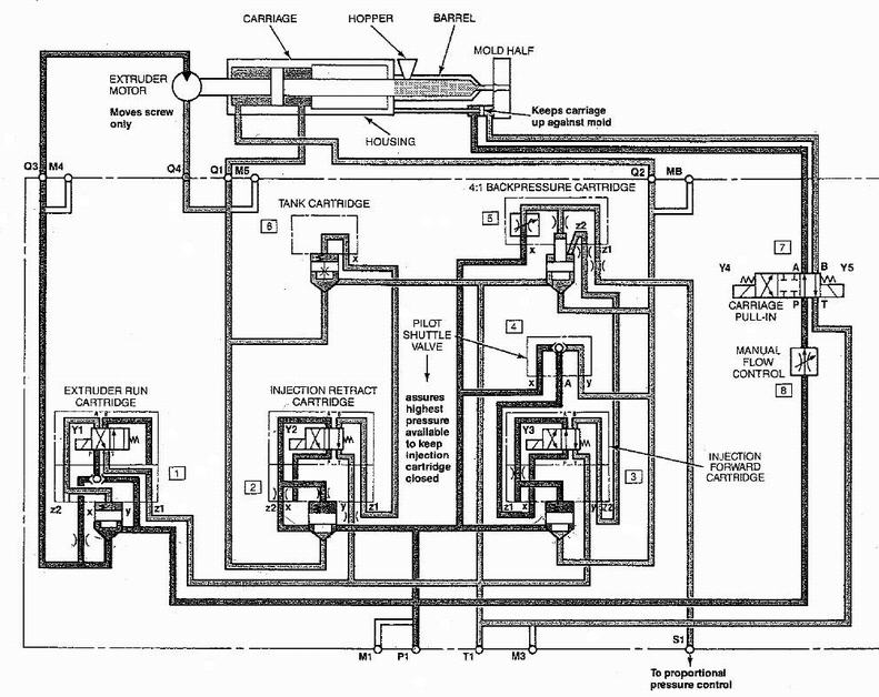
Figure 2. Injection Unit Hydraulic System
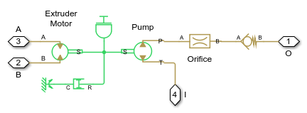
Extruder Subsystem
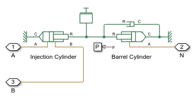
Injector Subsystem
Valve Manifold Subsystem
The valve manifold consists of five cartridge valves.
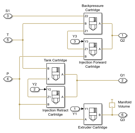
Extruder Cartridge Valve
The extruder cartridge valve controls the rotation of the extruder motor. The motor starts rotating when signal Y1 activates.

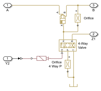
Injection Retract Cartridge Valve
The injection retract cartridge retracts the nozzle from the mold a short distance so that the mold can open to remove the previously molded and hardened part. The cartridge poppet opens when signal Y2 turns on. When the signal turns off, the poppet closes and the tank cartridge valve control chamber vents to allow free return flow from the extruder motor.
Tank Cartridge Valve
The tank cartridge valve connects the extruder motor to the tank during the barrel fill.

Injection Forward Cartridge Valve
The injection forward cartridge valve pushes the nozzle forward to contact the mold and inject molten plastic into the mold. Signal Y3 controls the cartridge. At the neutral position, one of the control chambers of the back-pressure cartridge vents to allow the cartridge to work as a pressure relief valve and maintain the pressure set by the supply pressure at port Z1 and the openings of orifices in the back-pressure cartridge covers.

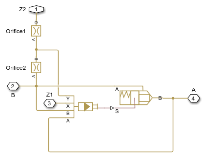
Backpressure Cartridge Valve
The back-pressure cartridge valve maintains low back-pressure in the injection cylinder chamber to ensure required quality of the molten plastic. The cartridge poppet opens when signal Y3 turns off. The back-pressure cartridge poppet closes simultaneously when the previously vented control chamber pressurizes.
Control Signals
There are five signals that control this system:
1. Extruder - Signal Y1
2. Retract - Signal Y2
3. Inject - Signal Y3
4. Nozzle - simulates the changing gap between the nozzle and the mold as a 2-way valve. In a real machine, the nozzle remains in contact with the mold while the extruder runs and the front portion of the barrel fills. This contact prevents molten plastic from spilling. Because this model does not include a mold, the 2-way valve controlled by the signal 'Nozzle' keeps the nozzle closed. The valve opens as the nozzle moves away from the mold to imitate real behavior.
5. Backpr - controls pressure level at port S1 (see also S1 in Figure 2), which establishes the pressure maintained by the back-pressure cartridge.
The model diagram (Figure 1) explains the purposes of the remaining blocks.
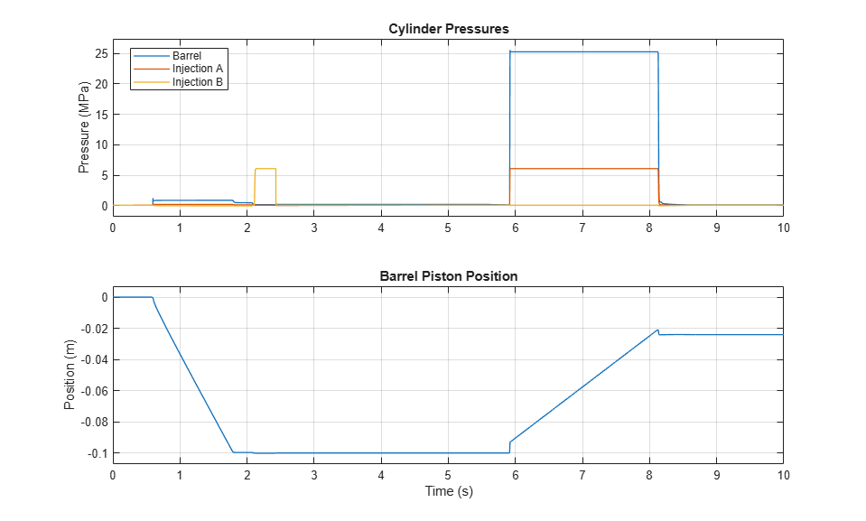
Simulation Results from Scopes

Simulation Results from Simscape Logging
These plots show the pressures in the injector chambers and the position of the barrel piston. The retraction, decompression, and injection phases can be identified by the pressures and positions in the system.