4-Way 3-Position Directional Valve (MA)
R2026b4-Way 3-Position Directional Valve (MA) block

To add a block to a model, double-click the canvas and start typing the block name. Then, select the block from the list.
Libraries:
Simscape /
Fluids /
Moist Air /
Valves & Orifices /
Directional Control Valves
Description
The 4-Way 3-Position Directional Valve (MA) block models a valve with four openings in a moist air network, typically between an actuator, pump, and tank. A single spool controls the valve operation according to the signal at port S. You can set the baseline configuration of your valve by specifying the orifices that are open when the spool is in the neutral position (centered at 0 m) in the Neutral spool position open connections parameter, when the spool moves in the positive direction in the Positive spool position open connections parameter, and when the spool moves in the negative direction in the Negative spool position open connections parameter. You can use the Orifice parameterization parameter to specify the valve model as a linear relationship or function of user-provided data.
This block is a composite component that comprises of multiple instances of the Orifice (MA) block. For more information about the valve parameterizations and block calculations, see the Orifice (MA) block.
In this example configuration, the Neutral spool position open
connections parameter is All closed. When the
spool is in the neutral position, all orifices are closed to flow:
In this configuration, Negative spool position open connections
is P-A, B-T. When the signal at port S
moves the spool to a negative position, the paths between ports P
and A and between ports B and
T are open to flow. The paths between ports
P and B and ports A
and T are closed to flow:
In this configuration, Positive spool position open connections
is P-B, A-T. When the signal at port S
moves the spool to a positive position, the paths between ports P
and B and between ports A and
T are open to flow and the paths between ports
P and A and between ports
B and T are closed:
This schematic shows this configuration:
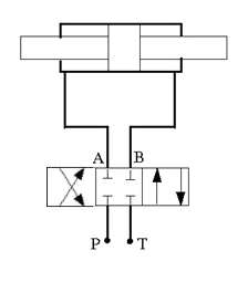
The left side corresponds to the positive position and the right side corresponds to the negative position.
Spool Displacement and Valve Configuration
The spool stroke is the amount of spool travel an orifice takes to fully open from a closed position. You can define the spool stroke using the parameters in the Valve Configuration section. The table shows how the block calculates the stroke in accordance with the valve orifice parameterization and flow path characteristics.
The direction of spool movement specified by port S depends on the spool stroke and the orifice orientation.
| Spool Position When Orifice Is Open | Spool Travel, ΔS |
|---|---|
| Always closed (orifice is not selected in any spool position configuration) | N/A |
| Always open (orifice is selected in positive, neutral, and negative spool position configurations) | N/A |
| Negative | Sorifice_max + spool stroke – S |
| Negative and Neutral | Sorifice_max + spool stroke – S |
| Positive | Sorifice_max – spool stroke + S |
| Positive and Neutral | Sorifice_max – spool stroke + S |
| Neutral | |Sorifice_max| + spool stroke – |S| |
| Positive and Negative | –|Sorifice_max| + spool stroke – |S| |
Sorifice_max is the spool position at the maximum orifice area defined for each orifice. The orifice area saturates at the leakage area when ΔS is negative and saturates at the maximum orifice area when the orifice is fully open. When the orifice is fully open, ΔS is equal to the spool stroke, so a value of ΔS that is greater than the spool stroke does not further increase the orifice area.
The Consistency check for neutral spool position open connections parameter verifies that:
Any orifice listed in Neutral spool position open connections is open when the signal at S is 0
Any orifice that is not listed in Neutral spool position open connections is closed when the signal at S is 0
You can optionally choose to receive a warning or error when any spool positions violate this check.
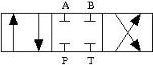
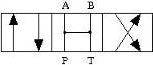
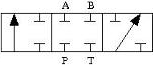
This table shows the possible configurations of the 4-Way 3-Position Directional Valve (MA) block.
| Configuration | Parameter Values |
|---|---|
| All four orifices are closed in the neutral position.
|
| All four orifices are open in the neutral position.
|
| Orifices A-T and B-T are closed. Orifices P-A and P-B are overlapped.
|
| Orifices A-T and B-T are open. Orifices P-A and P-B are overlapped.
|
| Orifices P-A and A-T are open in the neutral position. Orifices P-B and B-T are overlapped.
|
| Orifice A-T is open in the neutral position. Orifices P-B, A-T, and B-T are overlapped.
|
| Orifice B-T is open in the neutral position. Orifices P-A, P-B, and A-T are overlapped.
|
| Orifices P-A and P-B are open. Orifices A-T and B-T are overlapped.
|
| Orifice P-A is open in the neutral position. Orifices P-B, A-T, and B-T are overlapped.
|
| Orifice P-B is open in the neutral position. Orifices P-A, A-T, and B-T are overlapped.
|
| Orifices P-B and B-T are open in the neutral position. Orifices P-A and A-T are overlapped.
|
| Orifices P-A, P-B, A-T, and B-T are closed in the neutral position. P-T is open in the neutral position and closes when the spool displaces.
|
| Orifice P-A is a constant orifice. Orifices P-B, A-T, and B-T are open in the neutral position.
|
| Orifice P-B is a constant orifice. Orifices P-A, A-T, B-T are open in the neutral position.
|
| Orifice P-A is closed in the neutral position. Ports A and T do not form a flow path.
|
| Orifice P-B is closed in the neutral position. Ports B and T do not form a flow path.
|
| Orifice P-A is closed in the neutral position. Orifice A-T is open in the neutral position.
|
| Orifice P-B is closed in the neutral position. Orifice B-T is open in the neutral position.
|
| Orifice P-B is closed in the neutral position. Orifice P-T is open in the neutral position. Ports A and T do not form a flow path.
|
| Orifice P-A is closed in the neutral position. Orifice P-T is open in the neutral position. Ports A and T do not form a flow path.
|

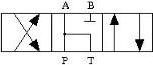
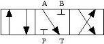
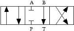
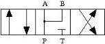
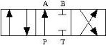
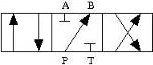
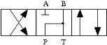
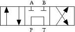
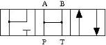
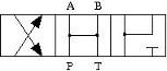
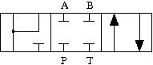
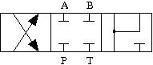
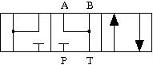
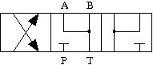
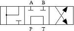
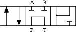
Valve Orifice Parameterizations
The Orifice parameterization parameter specifies the model
for the open area or flow rate through one or all of the valve orifices. If you set
Area characteristics to Identical for all flow
paths, the block applies the same data for all flow paths. When
you select Different for all flow paths, the block uses
individual parameterizations for each flow path.
The method the block uses to control each orifice depends on the Opening characteristic parameter:
Linear— The measure of flow capacity depends on the spool position at port S. As the spool displaces to open to orifice, the measure of flow capacity scales from the specified minimum to the specified maximum.Tabulated— The block calculates the measure of flow capacity as a function of the spool position at port S. This function uses a one-dimensional lookup table.
The Orifice parameterization parameter determines how the block calculates the flow rate in each orifice:
Cv flow coefficient— The flow coefficient Cv scales the flow rate in each orifice. The flow coefficient measures the ease with which a fluid can flow when driven by a certain pressure differential.Kv flow coefficient— The flow coefficient Kv, where , scales the flow rate in each orifice. The flow coefficient measures the ease with which a fluid can flow when driven by a certain pressure differential.Orifice area— The size of the orifice area scales the flow rate in each orifice.
Visualize Orifice Openings
To generate a characteristic plot of the valve, click the Plot button next to Valve characteristics. The plot shows the orifices selected in the Valve Configuration settings. The plot shows the sonic conductance, Kv flow coefficient, Cv flow coefficient, or orifice area as a function of spool position.
When the positive, neutral, and negative settings in the Valve Configuration parameters feature the same orifice, the plot displays the orifice openings as a constant.
To update the data after changing the block parameters, click Reload Data on the figure window.
This image shows an example valve configuration. In the Valve Configuration settings:
Positive spool position open connections is
P-A,
												B-T
Neutral spool position open connections is
P-TNegative spool position open connections is
P-B,
												A-T
In the P-A Orifice settings:
Spool position at maximum P-A orifice area is
2.5e-3 m
All other spool positions are at the default values.

The visualization shows that the P-A orifice is open between the spool position at
-2.53e-3 and 2.53e-3 m. Because the P-A
orifice is open only when the spool is displaced in the positive direction, setting
the Consistency check for neutral spool and position open
connections parameter to Warning
returns:
Warning: P-A orifice must be closed when the spool is in
the neutral position. Adjust Spool position at maximum P-A orifice area, Neutral
spool position open connections, or Consistency check for neutral spool position
open connections. Right-click on the block and select Fluids > Plot Valve
Characteristics to view the area or flow of each connection versus spool
position.
To resolve this warning, you can change:
Spool position at maximum P-A orifice area to a value larger than 0.005 m
Consistency check for neutral spool position open connections to
NoneThe valve configuration by setting Neutral spool position open connections to
P-A
Assumptions and Limitations
The
Sonic conductancesetting of the Valve parameterization parameter is for pneumatic applications. If you use this setting for moist air with high levels of trace gasses or are modeling a fluid other than air, you may need to scale the sonic conductance by the square root of the mixture specific gravity.This block does not model supersonic flow.
There is no heat exchange between the valve and the environment.
Ports
Conserving
Moist air conserving port associated with the entry or exit port to the valve.
Programmatic Use
Port:
A
Moist air conserving port associated with the entry or exit port to the valve.
Programmatic Use
Port:
B
Moist air conserving port associated with the entry or exit port to the valve.
Programmatic Use
Port:
P
Moist air conserving port associated with the entry or exit port to the valve.
Programmatic Use
Port:
T
Input
Physical signal associated with the spool displacement, in m.
Programmatic Use
Port:
S
Parameters
Valve Configuration
Flow paths open when the spool is in a positive position. This
parameter sets the valve configuration and defines the direction of
spool movement according to the signal received at port
S. To check the parameter settings for
consistency with other orifices, set Consistency check for
neutral spool position open connections to
Warning or
Error.
Programmatic Use
| Parameter: | open_orifices_pos |
| Values: | "fluids.moist_air.valves_orifices.directional_control_valves.enum.OpenOrifices4WayPosNeg.PA_BT" | "fluids.moist_air.valves_orifices.directional_control_valves.enum.OpenOrifices4WayPosNeg.PA_PB" | "fluids.moist_air.valves_orifices.directional_control_valves.enum.OpenOrifices4WayPosNeg.PB_AT" | "fluids.moist_air.valves_orifices.directional_control_valves.enum.OpenOrifices4WayPosNeg.PA" | "fluids.moist_air.valves_orifices.directional_control_valves.enum.OpenOrifices4WayPosNeg.PB" | "fluids.moist_air.valves_orifices.directional_control_valves.enum.OpenOrifices4WayPosNeg.PA_PB_AB" |
Flow paths open when the spool is in the neutral position. This
parameter sets the valve configuration and defines the direction of
spool movement according to the signal received at port
S. To check the parameter settings for
consistency with other orifices, set Consistency check for
neutral spool position open connections to
Warning or
Error.
Programmatic Use
| Parameter: | open_orifices_neu |
| Values: | "fluids.moist_air.valves_orifices.directional_control_valves.enum.OpenOrifices4WayNeu.AllClosed" | "fluids.moist_air.valves_orifices.directional_control_valves.enum.OpenOrifices4WayNeu.PA_PB_AT_BT" | "fluids.moist_air.valves_orifices.directional_control_valves.enum.OpenOrifices4WayNeu.AT_BT" | "fluids.moist_air.valves_orifices.directional_control_valves.enum.OpenOrifices4WayNeu.PA_AT" | "fluids.moist_air.valves_orifices.directional_control_valves.enum.OpenOrifices4WayNeu.PA_BT" | "fluids.moist_air.valves_orifices.directional_control_valves.enum.OpenOrifices4WayNeu.PA_PB" | "fluids.moist_air.valves_orifices.directional_control_valves.enum.OpenOrifices4WayNeu.PB_AT" | "fluids.moist_air.valves_orifices.directional_control_valves.enum.OpenOrifices4WayNeu.PB_BT" | "fluids.moist_air.valves_orifices.directional_control_valves.enum.OpenOrifices4WayNeu.AT" | "fluids.moist_air.valves_orifices.directional_control_valves.enum.OpenOrifices4WayNeu.BT" | "fluids.moist_air.valves_orifices.directional_control_valves.enum.OpenOrifices4WayNeu.PA" | "fluids.moist_air.valves_orifices.directional_control_valves.enum.OpenOrifices4WayNeu.PB" | "fluids.moist_air.valves_orifices.directional_control_valves.enum.OpenOrifices4WayNeu.PT" | "fluids.moist_air.valves_orifices.directional_control_valves.enum.OpenOrifices4WayNeu.PA_AT_PT" | "fluids.moist_air.valves_orifices.directional_control_valves.enum.OpenOrifices4WayNeu.PA_PB_AB" | "fluids.moist_air.valves_orifices.directional_control_valves.enum.OpenOrifices4WayNeu.PB_BT_PT" | "fluids.moist_air.valves_orifices.directional_control_valves.enum.OpenOrifices4WayNeu.PA_PB_AT_BT_PT" |
Flow paths open when the spool moves in the negative direction. This
parameter sets the valve configuration and defines the direction of
spool movement according to the signal received at port
S. To check the parameter settings for
consistency with other orifices, set Consistency check for
neutral spool position open connections to
Warning or
Error.
Programmatic Use
| Parameter: | open_orifices_neg |
| Values: | "fluids.moist_air.valves_orifices.directional_control_valves.enum.OpenOrifices4WayPosNeg.PA_BT" | "fluids.moist_air.valves_orifices.directional_control_valves.enum.OpenOrifices4WayPosNeg.PA_PB" | "fluids.moist_air.valves_orifices.directional_control_valves.enum.OpenOrifices4WayPosNeg.PB_AT" | "fluids.moist_air.valves_orifices.directional_control_valves.enum.OpenOrifices4WayPosNeg.PA" | "fluids.moist_air.valves_orifices.directional_control_valves.enum.OpenOrifices4WayPosNeg.PB" | "fluids.moist_air.valves_orifices.directional_control_valves.enum.OpenOrifices4WayPosNeg.PA_PB_AB" |
Whether to check if the neutral spool position open settings in the Valve Configuration section are consistent with the specified spool position at the maximum orifice area. For each enabled orifice, the actual offset at the spool neutral position should be commensurate with the specified spool offset for each individual orifice.
Programmatic Use
| Parameter: | neutral_assert_action |
| Values: | "simscape.enum.assert.action.warn" | "simscape.enum.assert.action.error" | "simscape.enum.assert.action.none" |
Model Parameterization
Whether to apply uniform or individual flow equations for the valve
orifice area. When you set this parameter to Identical for
all flow paths, the block uses the same orifice and
spool geometries, flow rates, pressure, and area vectors for all valve
orifices. When you set this parameter to Different for each
flow path, you can specify these parameters
individually for each orifice. For both settings, orifices
A, B,
P, and T have the same
cross-sectional areas, discharge coefficients, and Reynolds numbers when
you set Orifice parameterization to
Linear - Area vs. spool travel or
Tabulated data - Area vs. spool travel.
Programmatic Use
| Parameter: | area_spec |
| Values: | "fluids.moist_air.valves_orifices.directional_control_valves.enum.AreaSpec.Identical" | "fluids.moist_air.valves_orifices.directional_control_valves.enum.AreaSpec.Different" |
Method the block uses to calculate the mass flow rate from the pressure difference across the orifice or the pressure difference from the mass flow rate.
Programmatic Use
| Parameter: | valve_parameterization |
| Values: | "fluids.moist_air.valves_orifices.enum.OrificeParameterization.Cv" | "fluids.moist_air.valves_orifices.enum.OrificeParameterization.Kv" | "fluids.moist_air.valves_orifices.enum.OrificeParameterization.SonicConductance" | "fluids.moist_air.valves_orifices.enum.OrificeParameterization.Area" |
Maximum distance of spool travel.
Dependencies
To enable this parameter, set Area
characteristics to Identical for all
flow paths and Opening
characteristic to
Linear.
Programmatic Use
Parameter:
del_S_max
Method by which to convert the control signal specified at port S to the chosen measure of flow capacity.
Programmatic Use
| Parameter: | opening_characteristic |
| Values: | "fluids.moist_air.valves_orifices.enum.OpeningCharacteristics.Linear" | "fluids.moist_air.valves_orifices.enum.OpeningCharacteristics.Tabulated" |
Vector of spool travel distances when parameterizing the orifice according to the tabulated valve area data. The vector elements must correspond one-to-one with the elements in the Orifice area vector parameter. List the values in ascending order. The first element must be 0. The block uses linear interpolation between table data points.
Dependencies
To enable this parameter, set Area
characteristics to Identical for all
flow paths and Opening
characteristic to
Tabulated.
Programmatic Use
Parameter:
del_S_Cv_TLU
Parameter:
del_S_Kv_TLU
Parameter:
del_S_C_TLU
Parameter:
del_S_orifice_area_TLU
Value of the Cv flow coefficient when the orifice is fully open and the area available for flow is at a maximum. This parameter measures the ease with which the vapor traverses the resistive element when driven by a pressure differential.
Dependencies
To enable this parameter, set Area
characteristics to Identical for all
flow paths, Orifice
parameterization to Cv flow
coefficient, and Opening
characteristic to
Linear.
Programmatic Use
Parameter:
Cv_max
Vector of Cv flow coefficients. Each coefficient corresponds to a value in the Control member position vector parameter. This parameter measures the ease with which the vapor traverses the resistive element when driven by a pressure differential. The size of the vector must be the same as the Control member position vector parameter.
Dependencies
To enable this parameter, set Area
characteristics to Identical for all
flow paths, Orifice
parameterization to Cv flow
coefficient, and Opening
characteristic to
Tabulated.
Programmatic Use
Parameter:
Cv_TLU
Value of the Kv flow coefficient when the orifice is fully open and the area available for flow is at a maximum. This parameter measures the ease with which the vapor traverses the resistive element when driven by a pressure differential.
Dependencies
To enable this parameter, set Area
characteristics to Identical for all
flow paths, Orifice
parameterization to Kv flow
coefficient, and Opening
characteristic to
Linear.
Programmatic Use
Parameter:
Kv_max
Vector of Kv flow coefficients. Each coefficient corresponds to a value in the Control member position vector parameter. This parameter measures the ease with which the vapor traverses the resistive element when driven by a pressure differential. The size of the vector must be the same as the Control member position vector parameter.
Dependencies
To enable this parameter, set Area
characteristics to Identical for all
flow paths, Orifice
parameterization to Kv flow
coefficient, and Opening
characteristic to
Tabulated.
Programmatic Use
Parameter:
Kv_TLU
Largest open area of each orifice during the operation of the valve.
Dependencies
To enable this parameter, set Area
characteristics to Identical for all
flow paths, Orifice
parameterization to Orifice
area, and Opening
characteristic to
Linear.
Programmatic Use
Parameter:
orifice_area_max
Vector of opening areas when parameterizing the orifice according to the tabulated valve area data. The vector elements must correspond one-to-one with the elements in the Spool travel vector parameter. List the values in ascending order. The elements must be greater than 0. The first element of this vector is the leakage area.
Dependencies
To enable this parameter, set Area
characteristics to Identical for all
flow paths, Orifice
parameterization to Orifice
area, and Opening
characteristic to
Tabulated.
Programmatic Use
Parameter:
orifice_area_TLU
Ratio between the inlet pressure, pin, and the outlet pressure, pout, defined as where choking first occurs.
Dependencies
To enable this parameter, set Area
characteristics to Identical for all
flow paths, and Orifice
parameterization to Cv flow
coefficient or Kv flow
coefficient.
Programmatic Use
Parameter:
xT_Cv
Parameter:
xT_Kv
Correction factor that accounts for discharge losses in theoretical flows.
Dependencies
To enable this parameter, set Orifice
parameterization to Orifice
area.
Programmatic Use
Parameter:
Cd
Value of the sonic conductance when the control signal specified at
port S is 1 and
cross-sectional area available for flow is at a maximum.
Dependencies
To enable this parameter, set Area
characteristics to Identical for all
flow paths, Orifice
parameterization to Sonic
conductance, and Opening
characteristic to
Linear.
Programmatic Use
Parameter:
C_max
Pressure ratio at which flow first begins to choke and the flow velocity reaches its maximum, given by the local speed of sound. The pressure ratio is the outlet pressure divided by inlet pressure.
Dependencies
To enable this parameter, set Area
characteristics to Identical for all
flow paths, Orifice
parameterization to Sonic
conductance, and Opening
characteristic to
Linear.
Programmatic Use
Parameter:
B_crit_linear
Empirical value used to more accurately calculate the mass flow rate in the subsonic flow regime.
Dependencies
To enable this parameter, set Area
characteristics to Identical for all
flow paths and Orifice
parameterization to Sonic
conductance.
Programmatic Use
Parameter:
m
Temperature at standard reference atmosphere, defined as 293.15 K in ISO 8778.
You only need to adjust the ISO reference parameter values if you are using sonic conductance values that are obtained at difference reference values.
Dependencies
To enable this parameter, set Area
characteristics to Identical for all
flow paths and Orifice
parameterization to Sonic
conductance.
Programmatic Use
Parameter:
T_ref_C
Density at standard reference atmosphere, defined as 1.185 kg/m3 in ISO 8778.
You only need to adjust the ISO reference parameter values if you are using sonic conductance values that are obtained at difference reference values.
Dependencies
To enable this parameter, set Area
characteristics to Identical for all
flow paths and Orifice
parameterization to Sonic
conductance.
Programmatic Use
Parameter:
rho_ref_C
Vector of sonic conductances inside the resistive element. Each conductance corresponds to a value in the Spool travel vector parameter. The size of the vector must be the same as the Spool travel vector parameter.
Dependencies
To enable this parameter, set Area
characteristics to Identical for all
flow paths, Orifice
parameterization to Sonic
conductance, and Opening
characteristic to
Tabulated.
Programmatic Use
Parameter:
C_TLU
Vector of critical pressure ratios at which the flow first chokes, with each critical pressure ratio corresponding to a value in the Spool travel vector parameter. The critical pressure ratio is the fraction of downstream-to-upstream pressures at which the flow velocity reaches the local speed of sound. The size of the vector must be the same as the Spool travel vector parameter.
Dependencies
To enable this parameter, set Area
characteristics to Identical for all
flow paths, Orifice
parameterization to Sonic
conductance, and Opening
characteristic to
Tabulated.
Programmatic Use
Parameter:
B_crit_TLU
Ratio of the flow rate of the orifice when it is closed to when it is open.
Dependencies
To enable this parameter, set Opening
characteristic to
Linear.
Programmatic Use
Parameter:
leakage_fraction
Continuous smoothing factor that introduces a layer of gradual change based on the flow response when the valve is in the near-open and near-closed positions. To increase the stability of your simulation in these regimes, set this parameter to a nonzero value less than one.
Dependencies
To enable this parameter, set Opening
characteristic to
Linear.
Programmatic Use
Parameter:
smoothing_factor
Ratio of the orifice outlet pressure to orifice inlet pressure at which the fluid transitions between the laminar and turbulent regimes. The pressure loss corresponds to the mass flow rate linearly in laminar flows and quadratically in turbulent flows.
Programmatic Use
Parameter:
B_lam
Maximum cross-sectional areas at the entry and exit ports P, T, A, and B, which the block uses in the pressure-flow rate equation that determines the mass flow rate through the valve.
Programmatic Use
Parameter:
area
P-A Orifice
Spool offset from the neutral position for a fully open P-A orifice.
Dependencies
To enable this parameter, set one of these parameters.
Positive spool position open connections to:
P-A, B-TP-A, P-BP-AP-A, P-B, A-B
Neutral spool position open connections to:
P-A, P-B, A-T, B-TP-A, A-TP-A, B-TP-A, P-BP-AP-A, A-T, P-TP-A, P-B, A-BP-A, P-B, A-T, B-T, P-T
Negative spool position open connections to:
P-A, P-B, A-T, B-TP-A, A-TP-A, B-TP-A, P-BP-AP-A, P-B, A-B
Note:
This parameter is enabled only when the P-A orifice settings do not appear in all three spool position parameters: Positive spool position open connections, Neutral spool position open connections, and Negative spool position open connections.
Programmatic Use
Parameter:
S_max_PA
Maximum distance of spool travel. This value provides an upper limit to calculations so that simulations do not return unphysical values.
Dependencies
To enable this parameter, set Area
characteristics to Different for each
flow path, Opening
characteristic to Linear,
and one of the following parameters:
Positive spool position open connections to:
P-A, B-TP-A, P-BP-AP-A, P-B, A-B
Neutral spool position open connections to:
P-A, P-B, A-T, B-TP-A, A-TP-A, B-TP-A, P-BP-AP-A, A-T, P-TP-A, P-B, A-BP-A, P-B, A-T, B-T, P-T
Negative spool position open connections to:
P-A, P-B, A-T, B-TP-A, A-TP-A, B-TP-A, P-BP-AP-A, P-B, A-B
Programmatic Use
Parameter:
del_S_max_PA
Value of the constant Cv flow coefficient for the P-A orifice. This parameter measures the ease with which the vapor traverses the resistive element when driven by a pressure differential.
Dependencies
To enable this parameter, set:
Area characteristics to
Different for each flow pathOrifice parameterization to
Cv flow coefficientOne of the following settings in each parameter:
Positive spool position open connections to:
P-A, B-TP-A, P-BP-AP-A, P-B, A-B
Neutral spool position open connections to:
P-A, P-B, A-T, B-TP-A, A-TP-A, B-TP-A, P-BP-AP-A, A-T, P-TP-A, P-B, A-BP-A, P-B, A-T, B-T, P-T
Negative spool position open connections to:
P-A, P-B, A-T, B-TP-A, A-TP-A, B-TP-A, P-BP-AP-A, P-B, A-B
Note:
This parameter is enabled only when the P-A orifice settings appear all three spool position parameters: Positive spool position open connections, Neutral spool position open connections, and Negative spool position open connections.
Programmatic Use
Parameter:
Cv_const_PA
Value of the Cv flow coefficient when the P-A orifice is fully open and the area available for flow is at a maximum. This parameter measures the ease with which the vapor traverses the resistive element when driven by a pressure differential.
Dependencies
To enable this parameter, set:
Area characteristics to
Different for each flow pathOrifice parameterization to
Cv flow coefficientOpening characteristic to
LinearOne of the following parameters:
Positive spool position open connections to:
P-A, B-TP-A, P-BP-AP-A, P-B, A-B
Neutral spool position open connections to:
P-A, P-B, A-T, B-TP-A, A-TP-A, B-TP-A, P-BP-AP-A, A-T, P-TP-A, P-B, A-BP-A, P-B, A-T, B-T, P-T
Negative spool position open connections to:
P-A, P-B, A-T, B-TP-A, A-TP-A, B-TP-A, P-BP-AP-A, P-B, A-B
Programmatic Use
Parameter:
Cv_max_PA
Vector of Cv flow coefficients. Each coefficient corresponds to a value in the P-A orifice spool travel vector parameter. This parameter measures the ease with which the vapor traverses the resistive element when driven by a pressure differential. The size of the vector must be the same as the P-A orifice spool travel vector parameter.
Dependencies
To enable this parameter, set:
Area characteristics to
Different for each flow pathOrifice parameterization to
Cv flow coefficientOpening characteristic to
TabulatedOne of the following parameters:
Positive spool position open connections to:
P-A, B-TP-A, P-BP-AP-A, P-B, A-B
Neutral spool position open connections to:
P-A, P-B, A-T, B-TP-A, A-TP-A, B-TP-A, P-BP-AP-A, A-T, P-TP-A, P-B, A-BP-A, P-B, A-T, B-T, P-T
Negative spool position open connections to:
P-A, P-B, A-T, B-TP-A, A-TP-A, B-TP-A, P-BP-AP-A, P-B, A-B
Programmatic Use
Parameter:
Cv_TLU_PA
Value of the constant Kv flow coefficient for the P-A orifice. This parameter measures the ease with which the vapor traverses the resistive element when driven by a pressure differential.
Dependencies
To enable this parameter, set:
Area characteristics to
Different for each flow pathOrifice parameterization to
Kv flow coefficientOne of the following settings in each parameter:
Positive spool position open connections to:
P-A, B-TP-A, P-BP-AP-A, P-B, A-B
Neutral spool position open connections to:
P-A, P-B, A-T, B-TP-A, A-TP-A, B-TP-A, P-BP-AP-A, A-T, P-TP-A, P-B, A-BP-A, P-B, A-T, B-T, P-T
Negative spool position open connections to:
P-A, P-B, A-T, B-TP-A, A-TP-A, B-TP-A, P-BP-AP-A, P-B, A-B
Note:
This parameter is enabled only when the P-A orifice settings appear in all three spool position parameters: Positive spool position open connections, Neutral spool position open connections, and Negative spool position open connections.
Programmatic Use
Parameter:
Kv_const_PA
Value of the Kv flow coefficient when the P-A orifice is fully open and the area available for flow is at a maximum. This parameter measures the ease with which the vapor traverses the resistive element when driven by a pressure differential.
Dependencies
To enable this parameter, set:
Area characteristics to
Different for each flow pathOrifice parameterization to
Kv flow coefficientOpening characteristic to
LinearOne of the following parameters:
Positive spool position open connections to:
P-A, B-TP-A, P-BP-AP-A, P-B, A-B
Neutral spool position open connections to:
P-A, P-B, A-T, B-TP-A, A-TP-A, B-TP-A, P-BP-AP-A, A-T, P-TP-A, P-B, A-BP-A, P-B, A-T, B-T, P-T
Negative spool position open connections to:
P-A, P-B, A-T, B-TP-A, A-TP-A, B-TP-A, P-BP-AP-A, P-B, A-B
Programmatic Use
Parameter:
Kv_max_PA
Vector of Kv flow coefficients. Each coefficient corresponds to a value in the P-A orifice spool travel vector parameter. This parameter measures the ease with which the vapor traverses the resistive element when driven by a pressure differential. The size of the vector must be the same as the P-A orifice spool travel vector parameter.
Dependencies
To enable this parameter, set:
Area characteristics to
Different for each flow pathOrifice parameterization to
Kv flow coefficientOpening characteristic to
TabulatedOne of the following parameters:
Positive spool position open connections to:
P-A, B-TP-A, P-BP-AP-A, P-B, A-B
Neutral spool position open connections to:
P-A, P-B, A-T, B-TP-A, A-TP-A, B-TP-A, P-BP-AP-A, A-T, P-TP-A, P-B, A-BP-A, P-B, A-T, B-T, P-T
Negative spool position open connections to:
P-A, P-B, A-T, B-TP-A, A-TP-A, B-TP-A, P-BP-AP-A, P-B, A-B
Programmatic Use
Parameter:
Kv_TLU_PA
Vector of spool travel distances for the tabular parameterization of the valve area. List the values in ascending order. The first element must be 0. The block uses linear interpolation between table data points.
Dependencies
To enable this parameter, set Area
characteristics to Different for each
flow path, Opening
characteristic to
Tabulated, and one of the following
parameters:
Positive spool position open connections to:
P-A, B-TP-A, P-BP-AP-A, P-B, A-B
Neutral spool position open connections to:
P-A, P-B, A-T, B-TP-A, A-TP-A, B-TP-A, P-BP-AP-A, A-T, P-TP-A, P-B, A-BP-A, P-B, A-T, B-T, P-T
Negative spool position open connections to:
P-A, P-B, A-T, B-TP-A, A-TP-A, B-TP-A, P-BP-AP-A, P-B, A-B
Programmatic Use
Parameter:
del_S_Cv_TLU_PA
Parameter:
del_S_Kv_TLU_PA
Parameter:
del_S_C_TLU_PA
Parameter:
del_S_orifice_area_TLU_PA
Largest open area of the P-A orifice during the operation of the valve.
Dependencies
To enable this parameter, set:
Area characteristics to
Different for each flow pathOrifice parameterization to
Orifice areaOpening characteristic to
LinearOne of the following parameters:
Positive spool position open connections to:
P-A, B-TP-A, P-BP-AP-A, P-B, A-B
Neutral spool position open connections to:
P-A, P-B, A-T, B-TP-A, A-TP-A, B-TP-A, P-BP-AP-A, A-T, P-TP-A, P-B, A-BP-A, P-B, A-T, B-T, P-T
Negative spool position open connections to:
P-A, P-B, A-T, B-TP-A, A-TP-A, B-TP-A, P-BP-AP-A, P-B, A-B
Programmatic Use
Parameter:
orifice_area_max_PA
Vector of opening areas for the tabular parameterization of the valve area. The vector elements must correspond one-to-one with the elements in the P-A orifice spool travel vector parameter. The elements must be greater than 0 and listed in ascending order. The first element of this vector is the leakage area.
Dependencies
To enable this parameter, set:
Area characteristics to
Different for each flow pathOrifice parameterization to
Orifice areaOpening characteristic to
TabulatedOne of the following parameters:
Positive spool position open connections to:
P-A, B-TP-A, P-BP-AP-A, P-B, A-B
Neutral spool position open connections to:
P-A, P-B, A-T, B-TP-A, A-TP-A, B-TP-A, P-BP-AP-A, A-T, P-TP-A, P-B, A-BP-A, P-B, A-T, B-T, P-T
Negative spool position open connections to:
P-A, P-B, A-T, B-TP-A, A-TP-A, B-TP-A, P-BP-AP-A, P-B, A-B
Programmatic Use
Parameter:
orifice_area_TLU_PA
Orifice area when the positive and negative spool positions include the same orifice.
Dependencies
To enable this parameter, set:
Area characteristics to
Different for each flow pathOrifice parameterization to
Orifice areaOne of the following settings in each parameter:
Positive spool position open connections to:
P-A, B-TP-A, P-BP-AP-A, P-B, A-B
Neutral spool position open connections to:
P-A, P-B, A-T, B-TP-A, A-TP-A, B-TP-A, P-BP-AP-A, A-T, P-TP-A, P-B, A-BP-A, P-B, A-T, B-T, P-T
Negative spool position open connections to:
P-A, P-B, A-T, B-TP-A, A-TP-A, B-TP-A, P-BP-AP-A, P-B, A-B
Note:
This parameter is enabled only when the P-A orifice settings appear in all three spool position parameters: Positive spool position open connections, Neutral spool position open connections, and Negative spool position open connections.
Programmatic Use
Parameter:
orifice_area_const_PA
Ratio between the inlet pressure, pin, and the outlet pressure, pout, defined as where choking first occurs for the P-A orifice.
Dependencies
To enable this parameter, set:
Area characteristics to
Different for each flow pathOrifice parameterization to
Kv flow coefficientorCv flow coefficientAt least one of the following parameters:
Positive spool position open connections to:
P-A, B-TP-A, P-BP-AP-A, P-B, A-B
Neutral spool position open connections to:
P-A, P-B, A-T, B-TP-A, A-TP-A, B-TP-A, P-BP-AP-A, A-T, P-TP-A, P-B, A-BP-A, P-B, A-T, B-T, P-T
Negative spool position open connections to:
P-A, P-B, A-T, B-TP-A, A-TP-A, B-TP-A, P-BP-AP-A, P-B, A-B
Programmatic Use
Parameter:
xT_Cv_PA
Parameter:
xT_Kv_PA
Sonic conductance when the positive and negative spool positions include the same orifice. This value is the ratio, measured at the onset of choking, of the mass flow rate through the resistive element to the product of the upstream pressure and mass density at standard conditions as defined in ISO 8778. This parameter determines the maximum flow rate allowed at a given upstream pressure.
Dependencies
To enable this parameter, set:
Area characteristics to
Different for each flow pathOrifice parameterization to
Sonic conductanceOne of the following settings in each parameter:
Positive spool position open connections to:
P-A, B-TP-A, P-BP-AP-A, P-B, A-B
Neutral spool position open connections to:
P-A, P-B, A-T, B-TP-A, A-TP-A, B-TP-A, P-BP-AP-A, A-T, P-TP-A, P-B, A-BP-A, P-B, A-T, B-T, P-T
Negative spool position open connections to:
P-A, P-B, A-T, B-TP-A, A-TP-A, B-TP-A, P-BP-AP-A, P-B, A-B
Note:
This parameter is enabled only when the P-A orifice settings appear in all three spool position parameters: Positive spool position open connections, Neutral spool position open connections, and Negative spool position open connections.
Programmatic Use
Parameter:
C_const_PA
Critical pressure ratio when the positive and negative spool positions include the same orifice. This value is the pressure ratio at which flow first begins to choke and the flow velocity reaches its maximum, given by the local speed of sound. The pressure ratio is the outlet pressure divided by inlet pressure.
Dependencies
To enable this parameter, set:
Area characteristics to
Different for each flow pathOrifice parameterization to
Sonic conductanceOne of the following settings in each parameter:
Positive spool position open connections to:
P-A, B-TP-A, P-BP-AP-A, P-B, A-B
Neutral spool position open connections to:
P-A, P-B, A-T, B-TP-A, A-TP-A, B-TP-A, P-BP-AP-A, A-T, P-TP-A, P-B, A-BP-A, P-B, A-T, B-T, P-T
Negative spool position open connections to:
P-A, P-B, A-T, B-TP-A, A-TP-A, B-TP-A, P-BP-AP-A, P-B, A-B
Note:
This parameter is enabled only when the P-A orifice settings appear in all three spool position parameters: Positive spool position open connections, Neutral spool position open connections, and Negative spool position open connections.
Programmatic Use
Parameter:
B_crit_const_PA
Value of the sonic conductance when the P-A orifice is fully open and the area available for flow is at a maximum.
Dependencies
To enable this parameter, set:
Area characteristics to
Different for each flow pathOrifice parameterization to
Sonic conductanceOpening characteristic to
LinearOne of the following parameters:
Positive spool position open connections to:
P-A, B-TP-A, P-BP-AP-A, P-B, A-B
Neutral spool position open connections to:
P-A, P-B, A-T, B-TP-A, A-TP-A, B-TP-A, P-BP-AP-A, A-T, P-TP-A, P-B, A-BP-A, P-B, A-T, B-T, P-T
Negative spool position open connections to:
P-A, P-B, A-T, B-TP-A, A-TP-A, B-TP-A, P-BP-AP-A, P-B, A-B
Programmatic Use
Parameter:
C_max_PA
Pressure ratio at which flow first begins to choke and the flow velocity reaches its maximum, given by the local speed of sound. The pressure ratio is the outlet pressure divided by inlet pressure.
Dependencies
To enable this parameter, set:
Area characteristics to
Different for each flow pathOrifice parameterization to
Sonic conductanceOpening characteristic to
LinearOne of the following parameters:
Positive spool position open connections to:
P-A, B-TP-A, P-BP-AP-A, P-B, A-B
Neutral spool position open connections to:
P-A, P-B, A-T, B-TP-A, A-TP-A, B-TP-A, P-BP-AP-A, A-T, P-TP-A, P-B, A-BP-A, P-B, A-T, B-T, P-T
Negative spool position open connections to:
P-A, P-B, A-T, B-TP-A, A-TP-A, B-TP-A, P-BP-AP-A, P-B, A-B
Programmatic Use
Parameter:
B_crit_linear_PA
Vector of sonic conductances inside the resistive element. Each conductance corresponds to a value in the P-A orifice spool travel vector parameter. The size of the vector must be the same as the P-A orifice spool travel vector parameter.
Dependencies
To enable this parameter, set:
Area characteristics to
Different for each flow pathOrifice parameterization to
Sonic conductanceOpening characteristic to
TabulatedOne of the following parameters:
Positive spool position open connections to:
P-A, B-TP-A, P-BP-AP-A, P-B, A-B
Neutral spool position open connections to:
P-A, P-B, A-T, B-TP-A, A-TP-A, B-TP-A, P-BP-AP-A, A-T, P-TP-A, P-B, A-BP-A, P-B, A-T, B-T, P-T
Negative spool position open connections to:
P-A, P-B, A-T, B-TP-A, A-TP-A, B-TP-A, P-BP-AP-A, P-B, A-B
Programmatic Use
Parameter:
C_TLU_PA
Vector of critical pressure ratios at which the flow first chokes, with each critical pressure ratio corresponding to a value in the P-A orifice spool travel vector parameter. The critical pressure ratio is the fraction of downstream-to-upstream pressures at which the flow velocity reaches the local speed of sound. The size of the vector must be the same as the P-A orifice spool travel vector parameter.
Dependencies
To enable this parameter, set:
Area characteristics to
Different for each flow pathOrifice parameterization to
Sonic conductanceOpening characteristic to
TabulatedOne of the following parameters:
Positive spool position open connections to:
P-A, B-TP-A, P-BP-AP-A, P-B, A-B
Neutral spool position open connections to:
P-A, P-B, A-T, B-TP-A, A-TP-A, B-TP-A, P-BP-AP-A, A-T, P-TP-A, P-B, A-BP-A, P-B, A-T, B-T, P-T
Negative spool position open connections to:
P-A, P-B, A-T, B-TP-A, A-TP-A, B-TP-A, P-BP-AP-A, P-B, A-B
Programmatic Use
Parameter:
B_crit_TLU_PA
Empirical value used to more accurately calculate the mass flow rate in the subsonic flow regime.
Dependencies
To enable this parameter, set Area
characteristics to Different for each
flow path, Orifice
parameterization to Sonic
conductance, and at least one of the following
parameters:
Positive spool position open connections to:
P-A, B-TP-A, P-BP-AP-A, P-B, A-B
Neutral spool position open connections to:
P-A, P-B, A-T, B-TP-A, A-TP-A, B-TP-A, P-BP-AP-A, A-T, P-TP-A, P-B, A-BP-A, P-B, A-T, B-T, P-T
Negative spool position open connections to:
P-A, P-B, A-T, B-TP-A, A-TP-A, B-TP-A, P-BP-AP-A, P-B, A-B
Programmatic Use
Parameter:
m_PA
Temperature at standard reference atmosphere, defined as 293.15 K in ISO 8778.
You only need to adjust the ISO reference parameter values if you are using sonic conductance values that are obtained at difference reference values.
Dependencies
To enable this parameter, set Area
characteristics to Different for each
flow path, Orifice
parameterization to Sonic
conductance, and at least one of the following
parameters:
Positive spool position open connections to:
P-A, B-TP-A, P-BP-AP-A, P-B, A-B
Neutral spool position open connections to:
P-A, P-B, A-T, B-TP-A, A-TP-A, B-TP-A, P-BP-AP-A, A-T, P-TP-A, P-B, A-BP-A, P-B, A-T, B-T, P-T
Negative spool position open connections to:
P-A, P-B, A-T, B-TP-A, A-TP-A, B-TP-A, P-BP-AP-A, P-B, A-B
Programmatic Use
Parameter:
T_ref_C_PA
Density at standard reference atmosphere, defined as 1.185 kg/m3 in ISO 8778.
You only need to adjust the ISO reference parameter values if you are using sonic conductance values that are obtained at difference reference values.
Dependencies
To enable this parameter, set Area
characteristics to Different for each
flow path, Orifice
parameterization to Sonic
conductance, and at least one of the following
parameters:
Positive spool position open connections to:
P-A, B-TP-A, P-BP-AP-A, P-B, A-B
Neutral spool position open connections to:
P-A, P-B, A-T, B-TP-A, A-TP-A, B-TP-A, P-BP-AP-A, A-T, P-TP-A, P-B, A-BP-A, P-B, A-T, B-T, P-T
Negative spool position open connections to:
P-A, P-B, A-T, B-TP-A, A-TP-A, B-TP-A, P-BP-AP-A, P-B, A-B
Programmatic Use
Parameter:
rho_ref_C_PA
P-B Orifice
Spool offset from the neutral position for a fully open P-B orifice.
Dependencies
To enable this parameter, set one of these parameters:
Positive spool position open connections to:
P-B, A-TP-A, P-BP-BP-A, P-B, A-B
Neutral spool position open connections to:
P-A, P-B, A-T, B-TP-B, A-TP-B, B-TP-A, P-BP-BP-A, P-B, A-BP-B, B-T, P-TP-A, P-B, A-T, B-T, P-T
Negative spool position open connections to:
P-A, P-B, A-T, B-TP-B, A-TP-B, B-TP-A, P-BP-BP-A, P-B, A-B
Note:
This parameter is enabled only when the P-B orifice settings do not appear in all three spool position parameters: Positive spool position open connections, Neutral spool position open connections, and Negative spool position open connections.
Programmatic Use
Parameter:
S_max_PB
Maximum distance of spool travel. This value provides an upper limit to calculations so that simulations do not return unphysical values.
Dependencies
To enable this parameter, set Area
characteristics to Different for each
flow path, Opening
characteristic to Linear,
and one of the following parameters:
Positive spool position open connections to:
P-B, A-TP-A, P-BP-BP-A, P-B, A-B
Neutral spool position open connections to:
P-A, P-B, A-T, B-TP-B, A-TP-B, B-TP-A, P-BP-BP-A, P-B, A-BP-B, B-T, P-TP-A, P-B, A-T, B-T, P-T
Negative spool position open connections to:
P-A, P-B, A-T, B-TP-B, A-TP-B, B-TP-A, P-BP-BP-A, P-B, A-B
Programmatic Use
Parameter:
del_S_max_PB
Value of the constant Cv flow coefficient for the P-B orifice. This parameter measures the ease with which the vapor traverses the resistive element when driven by a pressure differential.
Dependencies
To enable this parameter, set:
Area characteristics to
Different for each flow pathOrifice parameterization to
Cv flow coefficientOne of the following settings in each parameter:
Positive spool position open connections to:
P-B, A-TP-A, P-BP-BP-A, P-B, A-B
Neutral spool position open connections to:
P-A, P-B, A-T, B-TP-B, A-TP-B, B-TP-A, P-BP-BP-A, P-B, A-BP-B, B-T, P-TP-A, P-B, A-T, B-T, P-T
Negative spool position open connections to:
P-A, P-B, A-T, B-TP-B, A-TP-B, B-TP-A, P-BP-BP-A, P-B, A-B
Note:
This parameter is enabled only when the P-B orifice settings appear in all three spool position parameters: Positive spool position open connections, Neutral spool position open connections, and Negative spool position open connections.
Programmatic Use
Parameter:
Cv_const_PB
Value of the Cv flow coefficient when the P-B orifice is fully open and the area available for flow is at a maximum. This parameter measures the ease with which the vapor traverses the resistive element when driven by a pressure differential.
Dependencies
To enable this parameter, set:
Area characteristics to
Different for each flow pathOrifice parameterization to
Cv flow coefficientOpening characteristic to
LinearOne of the following parameters:
Positive spool position open connections to:
P-B, A-TP-A, P-BP-BP-A, P-B, A-B
Neutral spool position open connections to:
P-A, P-B, A-T, B-TP-B, A-TP-B, B-TP-A, P-BP-BP-A, P-B, A-BP-B, B-T, P-TP-A, P-B, A-T, B-T, P-T
Negative spool position open connections to:
P-A, P-B, A-T, B-TP-B, A-TP-B, B-TP-A, P-BP-BP-A, P-B, A-B
Programmatic Use
Parameter:
Cv_max_PB
Vector of Cv flow coefficients. Each coefficient corresponds to a value in the P-B orifice spool travel vector parameter. This parameter measures the ease with which the vapor traverses the resistive element when driven by a pressure differential. The size of the vector must be the same as the P-B orifice spool travel vector parameter.
Dependencies
To enable this parameter, set:
Area characteristics to
Different for each flow pathOrifice parameterization to
Cv flow coefficientOpening characteristic to
TabulatedOne of the following parameters:
Positive spool position open connections to:
P-B, A-TP-A, P-BP-BP-A, P-B, A-B
Neutral spool position open connections to:
P-A, P-B, A-T, B-TP-B, A-TP-B, B-TP-A, P-BP-BP-A, P-B, A-BP-B, B-T, P-TP-A, P-B, A-T, B-T, P-T
Negative spool position open connections to:
P-A, P-B, A-T, B-TP-B, A-TP-B, B-TP-A, P-BP-BP-A, P-B, A-B
Programmatic Use
Parameter:
Cv_TLU_PB
Value of the constant Kv flow coefficient for the P-B orifice. This parameter measures the ease with which the vapor traverses the resistive element when driven by a pressure differential.
Dependencies
To enable this parameter, set:
Modeling option to
Vapor operating conditionArea characteristics to
Different for each flow pathOrifice parameterization to
Kv flow coefficientOne of the following settings in each parameter:
Positive spool position open connections to:
P-B, A-TP-A, P-BP-BP-A, P-B, A-B
Neutral spool position open connections to:
P-A, P-B, A-T, B-TP-B, A-TP-B, B-TP-A, P-BP-BP-A, P-B, A-BP-B, B-T, P-TP-A, P-B, A-T, B-T, P-T
Negative spool position open connections to:
P-A, P-B, A-T, B-TP-B, A-TP-B, B-TP-A, P-BP-BP-A, P-B, A-B
Note:
This parameter is enabled only when the P-B orifice settings appear in all three spool position parameters: Positive spool position open connections, Neutral spool position open connections, and Negative spool position open connections.
Programmatic Use
Parameter:
Kv_const_PB
Value of the Kv flow coefficient when the P-B orifice is fully open and the area available for flow is at a maximum. This parameter measures the ease with which the vapor traverses the resistive element when driven by a pressure differential.
Dependencies
To enable this parameter, set:
Area characteristics to
Different for each flow pathOrifice parameterization to
Kv flow coefficientOpening characteristic to
LinearOne of the following parameters:
Positive spool position open connections to:
P-B, A-TP-A, P-BP-BP-A, P-B, A-B
Neutral spool position open connections to:
P-A, P-B, A-T, B-TP-B, A-TP-B, B-TP-A, P-BP-BP-A, P-B, A-BP-B, B-T, P-TP-A, P-B, A-T, B-T, P-T
Negative spool position open connections to:
P-A, P-B, A-T, B-TP-B, A-TP-B, B-TP-A, P-BP-BP-A, P-B, A-B
Programmatic Use
Parameter:
Kv_max_PB
Vector of Kv flow coefficients. Each coefficient corresponds to a value in the P-B orifice spool travel vector parameter. This parameter measures the ease with which the vapor traverses the resistive element when driven by a pressure differential. The size of the vector must be the same as the P-B orifice spool travel vector parameter.
Dependencies
To enable this parameter, set:
Modeling option to
Vapor operating conditionArea characteristics to
Different for each flow pathOrifice parameterization to
Kv flow coefficientOpening characteristic to
TabulatedOne of the following parameters:
Positive spool position open connections to:
P-B, A-TP-A, P-BP-BP-A, P-B, A-B
Neutral spool position open connections to:
P-A, P-B, A-T, B-TP-B, A-TP-B, B-TP-A, P-BP-BP-A, P-B, A-BP-B, B-T, P-TP-A, P-B, A-T, B-T, P-T
Negative spool position open connections to:
P-A, P-B, A-T, B-TP-B, A-TP-B, B-TP-A, P-BP-BP-A, P-B, A-B
Programmatic Use
Parameter:
Kv_TLU_PB
Vector of spool travel distances for the tabular parameterization of the valve area. List the values in ascending order. The first element must be 0. The block uses linear interpolation between table data points.
Dependencies
To enable this parameter, set Area
characteristics to Different for each
flow path, Opening
characteristic to
Tabulated, and one of the following
parameters:
Positive spool position open connections to:
P-B, A-TP-A, P-BP-BP-A, P-B, A-B
Neutral spool position open connections to:
P-A, P-B, A-T, B-TP-B, A-TP-B, B-TP-A, P-BP-BP-A, P-B, A-BP-B, B-T, P-TP-A, P-B, A-T, B-T, P-T
Negative spool position open connections to:
P-A, P-B, A-T, B-TP-B, A-TP-B, B-TP-A, P-BP-BP-A, P-B, A-B
Programmatic Use
Parameter:
del_S_Cv_TLU_PB
Parameter:
del_S_Kv_TLU_PB
Parameter:
del_S_C_TLU_PB
Parameter:
del_S_orifice_area_TLU_PB
Largest open area of the P-B orifice during the operation of the valve.
Dependencies
To enable this parameter, set:
Area characteristics to
Different for each flow pathOrifice parameterization to
Orifice areaOpening characteristic to
TabulatedOne of the following parameters:
Positive spool position open connections to:
P-B, A-TP-A, P-BP-BP-A, P-B, A-B
Neutral spool position open connections to:
P-A, P-B, A-T, B-TP-B, A-TP-B, B-TP-A, P-BP-BP-A, P-B, A-BP-B, B-T, P-TP-A, P-B, A-T, B-T, P-T
Negative spool position open connections to:
P-A, P-B, A-T, B-TP-B, A-TP-B, B-TP-A, P-BP-BP-A, P-B, A-B
Programmatic Use
Parameter:
orifice_area_max_PB
Vector of opening areas for the tabular parameterization of the valve area. The vector elements must correspond one-to-one with the elements in the P-B orifice spool travel vector parameter. The elements must be greater than 0 and listed in ascending order. The first element of this vector is the leakage area.
Dependencies
To enable this parameter, set:
Area characteristics to
Different for each flow pathOrifice parameterization to
Orifice areaOpening characteristic to
TabulatedOne of the following parameters:
Positive spool position open connections to:
P-B, A-TP-A, P-BP-BP-A, P-B, A-B
Neutral spool position open connections to:
P-A, P-B, A-T, B-TP-B, A-TP-B, B-TP-A, P-BP-BP-A, P-B, A-BP-B, B-T, P-TP-A, P-B, A-T, B-T, P-T
Negative spool position open connections to:
P-A, P-B, A-T, B-TP-B, A-TP-B, B-TP-A, P-BP-BP-A, P-B, A-B
Programmatic Use
Parameter:
orifice_area_TLU_PB
Orifice area when the positive and negative spool positions include the same orifice.
Dependencies
To enable this parameter, set:
Area characteristics to
Different for each flow pathOrifice parameterization to
Orifice areaOne of the following settings in each parameter:
Positive spool position open connections to:
P-B, A-TP-A, P-BP-BP-A, P-B, A-B
Neutral spool position open connections to:
P-A, P-B, A-T, B-TP-B, A-TP-B, B-TP-A, P-BP-BP-A, P-B, A-BP-B, B-T, P-TP-A, P-B, A-T, B-T, P-T
Negative spool position open connections to:
P-A, P-B, A-T, B-TP-B, A-TP-B, B-TP-A, P-BP-BP-A, P-B, A-B
Note:
This parameter is enabled only when the P-B orifice settings appear in all three spool position parameters: Positive spool position open connections, Neutral spool position open connections, and Negative spool position open connections.
Programmatic Use
Parameter:
orifice_area_const_PB
Ratio between the inlet pressure, pin, and the outlet pressure, pout, defined as where choking first occurs for the P-B orifice.
Dependencies
To enable this parameter, set:
Area characteristics to
Different for each flow pathOrifice parameterization to
Kv flow coefficientorCv flow coefficientAt least one of the following parameters:
Positive spool position open connections to:
P-B, A-TP-A, P-BP-BP-A, P-B, A-B
Neutral spool position open connections to:
P-A, P-B, A-T, B-TP-B, A-TP-B, B-TP-A, P-BP-BP-A, P-B, A-BP-B, B-T, P-TP-A, P-B, A-T, B-T, P-T
Negative spool position open connections to:
P-A, P-B, A-T, B-TP-B, A-TP-B, B-TP-A, P-BP-BP-A, P-B, A-B
Programmatic Use
Parameter:
xT_Cv_PB
Parameter:
xT_Kv_PB
Sonic conductance when the positive and negative spool positions include the same orifice. This value is the ratio, measured at the onset of choking, of the mass flow rate through the resistive element to the product of the upstream pressure and mass density at standard conditions as defined in ISO 8778. This parameter determines the maximum flow rate allowed at a given upstream pressure.
Dependencies
To enable this parameter, set:
Area characteristics to
Different for each flow pathOrifice parameterization to
Sonic conductanceOne of the following settings in each parameter:
Positive spool position open connections to:
P-B, A-TP-A, P-BP-BP-A, P-B, A-B
Neutral spool position open connections to:
P-A, P-B, A-T, B-TP-B, A-TP-B, B-TP-A, P-BP-BP-A, P-B, A-BP-B, B-T, P-TP-A, P-B, A-T, B-T, P-T
Negative spool position open connections to:
P-A, P-B, A-T, B-TP-B, A-TP-B, B-TP-A, P-BP-BP-A, P-B, A-B
Note:
This parameter is enabled only when the P-B orifice settings appear in all three spool position parameters: Positive spool position open connections, Neutral spool position open connections, and Negative spool position open connections.
Programmatic Use
Parameter:
C_const_PB
Critical pressure ratio when the positive and negative spool positions include the same orifice. This value is the pressure ratio at which flow first begins to choke and the flow velocity reaches its maximum, given by the local speed of sound. The pressure ratio is the outlet pressure divided by inlet pressure.
Dependencies
To enable this parameter, set:
Area characteristics to
Different for each flow pathOrifice parameterization to
Sonic conductanceOne of the following settings in each parameter:
Positive spool position open connections to:
P-B, A-TP-A, P-BP-BP-A, P-B, A-B
Neutral spool position open connections to:
P-A, P-B, A-T, B-TP-B, A-TP-B, B-TP-A, P-BP-BP-A, P-B, A-BP-B, B-T, P-TP-A, P-B, A-T, B-T, P-T
Negative spool position open connections to:
P-A, P-B, A-T, B-TP-B, A-TP-B, B-TP-A, P-BP-BP-A, P-B, A-B
Note:
This parameter is enabled only when the P-B orifice settings appear in all three spool position parameters: Positive spool position open connections, Neutral spool position open connections, and Negative spool position open connections.
Programmatic Use
Parameter:
B_crit_const_PB
Value of the sonic conductance when the P-B orifice is fully open and the area available for flow is at a maximum.
Dependencies
To enable this parameter, set:
Area characteristics to
Different for each flow pathOrifice parameterization to
Sonic conductanceOpening characteristic to
LinearOne of the following parameters:
Positive spool position open connections to:
P-B, A-TP-A, P-BP-BP-A, P-B, A-B
Neutral spool position open connections to:
P-A, P-B, A-T, B-TP-B, A-TP-B, B-TP-A, P-BP-BP-A, P-B, A-BP-B, B-T, P-TP-A, P-B, A-T, B-T, P-T
Negative spool position open connections to:
P-A, P-B, A-T, B-TP-B, A-TP-B, B-TP-A, P-BP-BP-A, P-B, A-B
Programmatic Use
Parameter:
C_max_PB
Pressure ratio at which flow first begins to choke and the flow velocity reaches its maximum, given by the local speed of sound. The pressure ratio is the outlet pressure divided by inlet pressure.
Dependencies
To enable this parameter, set:
Area characteristics to
Different for each flow pathOrifice parameterization to
Sonic conductanceOpening characteristic to
LinearOne of the following parameters:
Positive spool position open connections to:
P-B, A-TP-A, P-BP-BP-A, P-B, A-B
Neutral spool position open connections to:
P-A, P-B, A-T, B-TP-B, A-TP-B, B-TP-A, P-BP-BP-A, P-B, A-BP-B, B-T, P-TP-A, P-B, A-T, B-T, P-T
Negative spool position open connections to:
P-A, P-B, A-T, B-TP-B, A-TP-B, B-TP-A, P-BP-BP-A, P-B, A-B
Programmatic Use
Parameter:
B_crit_linear_PB
Vector of sonic conductances inside the resistive element. Each conductance corresponds to a value in the P-B orifice spool travel vector parameter. The size of the vector must be the same as the P-B orifice spool travel vector parameter.
Dependencies
To enable this parameter, set:
Area characteristics to
Different for each flow pathOrifice parameterization to
Sonic conductanceOpening characteristic to
TabulatedOne of the following parameters:
Positive spool position open connections to:
P-B, A-TP-A, P-BP-BP-A, P-B, A-B
Neutral spool position open connections to:
P-A, P-B, A-T, B-TP-B, A-TP-B, B-TP-A, P-BP-BP-A, P-B, A-BP-B, B-T, P-TP-A, P-B, A-T, B-T, P-T
Negative spool position open connections to:
P-A, P-B, A-T, B-TP-B, A-TP-B, B-TP-A, P-BP-BP-A, P-B, A-B
Programmatic Use
Parameter:
C_TLU_PB
Vector of critical pressure ratios at which the flow first chokes, with each critical pressure ratio corresponding to a value in the P-B orifice spool travel vector parameter. The critical pressure ratio is the fraction of downstream-to-upstream pressures at which the flow velocity reaches the local speed of sound. The size of the vector must be the same as the P-B orifice spool travel vector parameter.
Dependencies
To enable this parameter, set:
Area characteristics to
Different for each flow pathOrifice parameterization to
Sonic conductanceOpening characteristic to
TabulatedOne of the following parameters:
Positive spool position open connections to:
P-B, A-TP-A, P-BP-BP-A, P-B, A-B
Neutral spool position open connections to:
P-A, P-B, A-T, B-TP-B, A-TP-B, B-TP-A, P-BP-BP-A, P-B, A-BP-B, B-T, P-TP-A, P-B, A-T, B-T, P-T
Negative spool position open connections to:
P-A, P-B, A-T, B-TP-B, A-TP-B, B-TP-A, P-BP-BP-A, P-B, A-B
Programmatic Use
Parameter:
B_crit_TLU_PB
Empirical value used to more accurately calculate the mass flow rate in the subsonic flow regime.
Dependencies
To enable this parameter, set Area
characteristics to Different for each
flow path, Orifice
parameterization to Sonic
conductance, and at least one of the following
parameters:
Positive spool position open connections to:
P-B, A-TP-A, P-BP-BP-A, P-B, A-B
Neutral spool position open connections to:
P-A, P-B, A-T, B-TP-B, A-TP-B, B-TP-A, P-BP-BP-A, P-B, A-BP-B, B-T, P-TP-A, P-B, A-T, B-T, P-T
Negative spool position open connections to:
P-A, P-B, A-T, B-TP-B, A-TP-B, B-TP-A, P-BP-BP-A, P-B, A-B
Programmatic Use
Parameter:
m_PB
Temperature at standard reference atmosphere, defined as 293.15 K in ISO 8778.
You only need to adjust the ISO reference parameter values if you are using sonic conductance values that are obtained at difference reference values.
Dependencies
To enable this parameter, set Area
characteristics to Different for each
flow path, Orifice
parameterization to Sonic
conductance, and at least one of the following
parameters:
Positive spool position open connections to:
P-B, A-TP-A, P-BP-BP-A, P-B, A-B
Neutral spool position open connections to:
P-A, P-B, A-T, B-TP-B, A-TP-B, B-TP-A, P-BP-BP-A, P-B, A-BP-B, B-T, P-TP-A, P-B, A-T, B-T, P-T
Negative spool position open connections to:
P-A, P-B, A-T, B-TP-B, A-TP-B, B-TP-A, P-BP-BP-A, P-B, A-B
Programmatic Use
Parameter:
T_ref_C_PB
Density at standard reference atmosphere, defined as 1.185 kg/m3 in ISO 8778.
You only need to adjust the ISO reference parameter values if you are using sonic conductance values that are obtained at difference reference values.
Dependencies
To enable this parameter, set Area
characteristics to Different for each
flow path, Orifice
parameterization to Sonic
conductance, and at least one of the following
parameters:
Positive spool position open connections to:
P-B, A-TP-A, P-BP-BP-A, P-B, A-B
Neutral spool position open connections to:
P-A, P-B, A-T, B-TP-B, A-TP-B, B-TP-A, P-BP-BP-A, P-B, A-BP-B, B-T, P-TP-A, P-B, A-T, B-T, P-T
Negative spool position open connections to:
P-A, P-B, A-T, B-TP-B, A-TP-B, B-TP-A, P-BP-BP-A, P-B, A-B
Programmatic Use
Parameter:
rho_ref_C_PB
A-B Orifice
Spool offset from the neutral position for a fully open A-B orifice.
Dependencies
To enable this parameter, set one of these parameters.
Positive spool position open connections to:
P-A, P-B, A-B
Neutral spool position open connections to:
P-A, P-B, A-B
Negative spool position open connections to:
P-A, P-B, A-B
Note:
This parameter is enabled only when the A-B orifice settings do not appear in all three spool position parameters: Positive spool position open connections, Neutral spool position open connections, and Negative spool position open connections.
Programmatic Use
Parameter:
S_max_AB
Maximum distance of spool travel. This value provides an upper limit to calculations so that simulations do not return unphysical values.
Dependencies
To enable this parameter, set Area
characteristics to Different for each
flow path, Opening
characteristic to Linear
one of the following parameters:
Positive spool position open connections to:
P-A, P-B, A-B
Neutral spool position open connections to:
P-A, P-B, A-B
Negative spool position open connections to:
P-A, P-B, A-B
Programmatic Use
Parameter:
del_S_max_AB
Value of the constant Cv flow coefficient for the A-B orifice. This parameter measures the ease with which the vapor traverses the resistive element when driven by a pressure differential.
Dependencies
To enable this parameter, set:
Area characteristics to
Different for each flow pathOrifice parameterization to
Cv flow coefficientOne of the following settings in each parameter:
Positive spool position open connections to:
P-A, P-B, A-B
Neutral spool position open connections to:
P-A, P-B, A-B
Negative spool position open connections to:
P-A, P-B, A-B
Note:
This parameter is enabled only when the A-B orifice settings appear all three spool position parameters: Positive spool position open connections, Neutral spool position open connections, and Negative spool position open connections.
Programmatic Use
Parameter:
Cv_const_AB
Value of the Cv flow coefficient when the A-B orifice is fully open and the area available for flow is at a maximum. This parameter measures the ease with which the vapor traverses the resistive element when driven by a pressure differential.
Dependencies
To enable this parameter, set:
Area characteristics to
Different for each flow pathOrifice parameterization to
Cv flow coefficientOpening characteristic to
LinearOne of the following parameters:
Positive spool position open connections to:
P-A, P-B, A-B
Neutral spool position open connections to:
P-A, P-B, A-B
Negative spool position open connections to:
P-A, P-B, A-B
Programmatic Use
Parameter:
Cv_max_AB
Vector of Cv flow coefficients. Each coefficient corresponds to a value in the A-B orifice spool travel vector parameter. This parameter measures the ease with which the vapor traverses the resistive element when driven by a pressure differential. The size of the vector must be the same as the A-B orifice spool travel vector parameter.
Dependencies
To enable this parameter, set:
Area characteristics to
Different for each flow pathOrifice parameterization to
Cv flow coefficientOpening characteristic to
TabulatedOne of the following parameters:
Positive spool position open connections to:
P-A, P-B, A-B
Neutral spool position open connections to:
P-A, P-B, A-B
Negative spool position open connections to:
P-A, P-B, A-B
Programmatic Use
Parameter:
Cv_TLU_AB
Value of the constant Kv flow coefficient for the A-B orifice. This parameter measures the ease with which the vapor traverses the resistive element when driven by a pressure differential.
Dependencies
To enable this parameter, set:
Area characteristics to
Different for each flow pathOrifice parameterization to
Kv flow coefficientOne of the following settings in each parameter:
Positive spool position open connections to:
P-A, P-B, A-B
Neutral spool position open connections to:
P-A, P-B, A-B
Negative spool position open connections to:
P-A, P-B, A-B
Note:
This parameter is enabled only when the A-B orifice settings appear in all three spool position parameters: Positive spool position open connections, Neutral spool position open connections, and Negative spool position open connections.
Programmatic Use
Parameter:
Kv_const_AB
Value of the Kv flow coefficient when the A-B orifice is fully open and the area available for flow is at a maximum. This parameter measures the ease with which the vapor traverses the resistive element when driven by a pressure differential.
Dependencies
To enable this parameter, set:
Area characteristics to
Different for each flow pathOrifice parameterization to
Kv flow coefficientOpening characteristic to
LinearOne of the following parameters:
Positive spool position open connections to:
P-A, P-B, A-B
Neutral spool position open connections to:
P-A, P-B, A-B
Negative spool position open connections to:
P-A, P-B, A-B
Programmatic Use
Parameter:
Kv_max_AB
Vector of Kv flow coefficients. Each coefficient corresponds to a value in the A-B orifice spool travel vector parameter. This parameter measures the ease with which the vapor traverses the resistive element when driven by a pressure differential. The size of the vector must be the same as the A-B orifice spool travel vector parameter.
Dependencies
To enable this parameter, set:
Area characteristics to
Different for each flow pathOrifice parameterization to
Kv flow coefficientOpening characteristic to
TabulatedOne of the following parameters:
Positive spool position open connections to:
P-A, P-B, A-B
Neutral spool position open connections to:
P-A, P-B, A-B
Negative spool position open connections to:
P-A, P-B, A-B
Programmatic Use
Parameter:
Kv_TLU_AB
Vector of spool travel distances for the tabular parameterization of the valve area. List the values in ascending order. The first element must be 0. The block uses linear interpolation between table data points.
Dependencies
To enable this parameter, set Area
characteristics to Different for each
flow path, Opening
characteristic to
Tabulated, and one of the following
parameters:
Positive spool position open connections to:
P-A, P-B, A-B
Neutral spool position open connections to:
P-A, P-B, A-B
Negative spool position open connections to:
P-A, P-B, A-B
Programmatic Use
Parameter:
del_S_Cv_TLU_AB
Parameter:
del_S_Kv_TLU_AB
Parameter:
del_S_C_TLU_AB
Parameter:
del_S_orifice_area_TLU_AB
Largest open area of the A-B orifice during the operation of the valve.
Dependencies
To enable this parameter, set:
Area characteristics to
Different for each flow pathOrifice parameterization to
Orifice areaOpening characteristic to
LinearOne of the following parameters:
Positive spool position open connections to:
P-A, P-B, A-B
Neutral spool position open connections to:
P-A, P-B, A-B
Negative spool position open connections to:
P-A, P-B, A-B
Programmatic Use
Parameter:
orifice_area_max_AB
Vector of opening areas for the tabular parameterization of the valve area. The vector elements must correspond one-to-one with the elements in the A-B orifice spool travel vector parameter. The elements must be greater than 0 and listed in ascending order. The first element of this vector is the leakage area.
Dependencies
To enable this parameter, set:
Area characteristics to
Different for each flow pathOrifice parameterization to
Orifice areaOpening characteristic to
TabulatedOne of the following parameters:
Positive spool position open connections to:
P-A, P-B, A-B
Neutral spool position open connections to:
P-A, P-B, A-B
Negative spool position open connections to:
P-A, P-B, A-B
Programmatic Use
Parameter:
orifice_area_TLU_AB
Orifice area when the positive and negative spool positions include the same orifice.
Dependencies
To enable this parameter, set:
Area characteristics to
Different for each flow pathOrifice parameterization to
Orifice areaOne of the following settings in each parameter:
Positive spool position open connections to:
P-A, P-B, A-B
Neutral spool position open connections to:
P-A, P-B, A-B
Negative spool position open connections to:
P-A, P-B, A-B
Note:
This parameter is enabled only when the A-B orifice settings appear in all three spool position parameters: Positive spool position open connections, Neutral spool position open connections, and Negative spool position open connections.
Programmatic Use
Parameter:
orifice_area_const_AB
Ratio between the inlet pressure, pin, and the outlet pressure, pout, defined as where choking first occurs for the A-B orifice.
Dependencies
To enable this parameter, set:
Area characteristics to
Different for each flow pathOrifice parameterization to
Kv flow coefficientorCv flow coefficientAt least one of the following parameters:
Positive spool position open connections to:
P-A, P-B, A-B
Neutral spool position open connections to:
P-A, P-B, A-B
Negative spool position open connections to:
P-A, P-B, A-B
Programmatic Use
Parameter:
xT_Cv_AB
Parameter:
xT_Kv_AB
Sonic conductance when the positive and negative spool positions include the same orifice. This value is the ratio, measured at the onset of choking, of the mass flow rate through the resistive element to the product of the upstream pressure and mass density at standard conditions as defined in ISO 8778. This parameter determines the maximum flow rate allowed at a given upstream pressure.
Dependencies
To enable this parameter, set:
Area characteristics to
Different for each flow pathOrifice parameterization to
Sonic conductanceOne of the following settings in each parameter:
Positive spool position open connections to:
P-A, P-B, A-B
Neutral spool position open connections to:
P-A, P-B, A-B
Negative spool position open connections to:
P-A, P-B, A-B
Note:
This parameter is enabled only when the A-B orifice settings appear in all three spool position parameters: Positive spool position open connections, Neutral spool position open connections, and Negative spool position open connections.
Programmatic Use
Parameter:
C_const_AB
Critical pressure ratio when the positive and negative spool positions include the same orifice. This value is the pressure ratio at which flow first begins to choke and the flow velocity reaches its maximum, given by the local speed of sound. The pressure ratio is the outlet pressure divided by inlet pressure.
Dependencies
To enable this parameter, set:
Area characteristics to
Different for each flow pathOrifice parameterization to
Sonic conductanceOne of the following settings in each parameter:
Positive spool position open connections to:
P-A, P-B, A-B
Neutral spool position open connections to:
P-A, P-B, A-B
Negative spool position open connections to:
P-A, P-B, A-B
Note:
This parameter is enabled only when the A-B orifice settings appear in all three spool position parameters: Positive spool position open connections, Neutral spool position open connections, and Negative spool position open connections.
Programmatic Use
Parameter:
B_crit_const_AB
Value of the sonic conductance when the A-B orifice is fully open and the area available for flow is at a maximum.
Dependencies
To enable this parameter, set:
Area characteristics to
Different for each flow pathOrifice parameterization to
Sonic conductanceOpening characteristic to
LinearOne of the following parameters:
Positive spool position open connections to:
P-A, P-B, A-B
Neutral spool position open connections to:
P-A, P-B, A-B
Negative spool position open connections to:
P-A, P-B, A-B
Programmatic Use
Parameter:
C_max_AB
Pressure ratio at which flow first begins to choke and the flow velocity reaches its maximum, given by the local speed of sound. The pressure ratio is the outlet pressure divided by inlet pressure.
Dependencies
To enable this parameter, set:
Area characteristics to
Different for each flow pathOrifice parameterization to
Sonic conductanceOpening characteristic to
LinearOne of the following parameters:
Positive spool position open connections to:
P-A, P-B, A-B
Neutral spool position open connections to:
P-A, P-B, A-B
Negative spool position open connections to:
P-A, P-B, A-B
Programmatic Use
Parameter:
B_crit_linear_AB
Vector of sonic conductances inside the resistive element. Each conductance corresponds to a value in the A-B orifice spool travel vector parameter. The size of the vector must be the same as the A-B orifice spool travel vector parameter.
Dependencies
To enable this parameter, set:
Area characteristics to
Different for each flow pathOrifice parameterization to
Sonic conductanceOpening characteristic to
TabulatedOne of the following parameters:
Positive spool position open connections to:
P-A, P-B, A-B
Neutral spool position open connections to:
P-A, P-B, A-B
Negative spool position open connections to:
P-A, P-B, A-B
Programmatic Use
Parameter:
C_TLU_AB
Vector of critical pressure ratios at which the flow first chokes, with each critical pressure ratio corresponding to a value in the A-B orifice spool travel vector parameter. The critical pressure ratio is the fraction of downstream-to-upstream pressures at which the flow velocity reaches the local speed of sound. The size of the vector must be the same as the A-B orifice spool travel vector parameter.
Dependencies
To enable this parameter, set:
Area characteristics to
Different for each flow pathOrifice parameterization to
Sonic conductanceOpening characteristic to
TabulatedOne of the following parameters:
Positive spool position open connections to:
P-A, P-B, A-B
Neutral spool position open connections to:
P-A, P-B, A-B
Negative spool position open connections to:
P-A, P-B, A-B
Programmatic Use
Parameter:
B_crit_TLU_AB
Empirical value used to more accurately calculate the mass flow rate in the subsonic flow regime.
Dependencies
To enable this parameter, set Area
characteristics to Different for each
flow path, Orifice
parameterization to Sonic
conductance, and at least one of the following
parameters:
Positive spool position open connections to:
P-A, P-B, A-B
Neutral spool position open connections to:
P-A, P-B, A-B
Negative spool position open connections to:
P-A, P-B, A-B
Programmatic Use
Parameter:
m_AB
Temperature at standard reference atmosphere, defined as 293.15 K in ISO 8778.
You only need to adjust the ISO reference parameter values if you are using sonic conductance values that are obtained at difference reference values.
Dependencies
To enable this parameter, set Area
characteristics to Different for each
flow path, Orifice
parameterization to Sonic
conductance, and at least one of the following
parameters:
Positive spool position open connections to:
P-A, P-B, A-B
Neutral spool position open connections to:
P-A, P-B, A-B
Negative spool position open connections to:
P-A, P-B, A-B
Programmatic Use
Parameter:
T_ref_C_AB
Density at standard reference atmosphere, defined as 1.185 kg/m3 in ISO 8778.
You only need to adjust the ISO reference parameter values if you are using sonic conductance values that are obtained at difference reference values.
Dependencies
To enable this parameter, set Area
characteristics to Different for each
flow path, Orifice
parameterization to Sonic
conductance, and at least one of the following
parameters:
Positive spool position open connections to:
P-A, P-B, A-B
Neutral spool position open connections to:
P-A, P-B, A-B
Negative spool position open connections to:
P-A, P-B, A-B
Programmatic Use
Parameter:
rho_ref_C_AB
A-T Orifice
Spool offset from the neutral position for a fully open A-T orifice.
Dependencies
To enable this parameter, set one of these parameters.
Positive spool position open connections to
P-B, A-T.Neutral spool position open connections to:
P-A, P-B, A-T, B-TP-B, A-TA-T, B-TP-A, A-TA-TP-A, A-T, P-TP-A, P-B, A-T, B-T, P-T
Negative spool position open connections to
P-B, A-T.
Note:
This parameter is enabled only when the A-T orifice settings do not appear in all three spool position parameters: Positive spool position open connections, Neutral spool position open connections, and Negative spool position open connections.
Programmatic Use
Parameter:
S_max_AT
Maximum distance of spool travel. This value provides an upper limit to calculations so that simulations do not return unphysical values.
Dependencies
To enable this parameter, set Area
characteristics to Different for each
flow path, Opening
characteristic to Linear,
and one of the following parameters:
Positive spool position open connections to
P-B, A-T.Neutral spool position open connections to:
P-A, P-B, A-T, B-TP-B, A-TA-T, B-TP-A, A-TA-TP-A, A-T, P-TP-A, P-B, A-T, B-T, P-T
Negative spool position open connections to
P-B, A-T.
Programmatic Use
Parameter:
del_S_max_AT
Value of the constant Cv flow coefficient for the A-T orifice. This parameter measures the ease with which the vapor traverses the resistive element when driven by a pressure differential.
Dependencies
To enable this parameter, set:
Area characteristics to
Different for each flow pathOrifice parameterization to
Cv flow coefficientOne of the following settings in each parameter:
Positive spool position open connections to
P-B, A-T.Neutral spool position open connections to:
P-A, P-B, A-T, B-TP-B, A-TA-T, B-TP-A, A-TA-TP-A, A-T, P-TP-A, P-B, A-T, B-T, P-T
Negative spool position open connections to
P-B, A-T.
Note:
This parameter is enabled only when the A-T orifice settings appear in all three spool position parameters: Positive spool position open connections, Neutral spool position open connections, and Negative spool position open connections.
Programmatic Use
Parameter:
Cv_const_AT
Value of the Cv flow coefficient when the A-T orifice is fully open and the area available for flow is at a maximum. This parameter measures the ease with which the vapor traverses the resistive element when driven by a pressure differential.
Dependencies
To enable this parameter, set:
Area characteristics to
Different for each flow pathOrifice parameterization to
Cv flow coefficientOpening characteristic to
LinearOne of the following parameters:
Positive spool position open connections to
P-B, A-T.Neutral spool position open connections to:
P-A, P-B, A-T, B-TP-B, A-TA-T, B-TP-A, A-TA-TP-A, A-T, P-TP-A, P-B, A-T, B-T, P-T
Negative spool position open connections to
P-B, A-T.
Programmatic Use
Parameter:
Cv_max_AT
Vector of Cv flow coefficients. Each coefficient corresponds to a value in the A-T orifice spool travel vector parameter. This parameter measures the ease with which the vapor traverses the resistive element when driven by a pressure differential. The size of the vector must be the same as the A-T orifice spool travel vector parameter.
Dependencies
To enable this parameter, set:
Area characteristics to
Different for each flow pathOrifice parameterization to
Cv flow coefficientOpening characteristic to
TabulatedOne of the following parameters:
Positive spool position open connections to
P-B, A-T.Neutral spool position open connections to:
P-A, P-B, A-T, B-TP-B, A-TA-T, B-TP-A, A-TA-TP-A, A-T, P-TP-A, P-B, A-T, B-T, P-T
Negative spool position open connections to
P-B, A-T.
Programmatic Use
Parameter:
Cv_TLU_AT
Value of the constant Kv flow coefficient for the A-T orifice. This parameter measures the ease with which the vapor traverses the resistive element when driven by a pressure differential.
Dependencies
To enable this parameter, set:
Area characteristics to
Different for each flow pathOrifice parameterization to
Kv flow coefficientOne of the following settings in each parameter:
Positive spool position open connections to
P-B, A-T.Neutral spool position open connections to:
P-A, P-B, A-T, B-TP-B, A-TA-T, B-TP-A, A-TA-TP-A, A-T, P-TP-A, P-B, A-T, B-T, P-T
Negative spool position open connections to
P-B, A-T.
Note:
This parameter is enabled only when the A-T orifice settings appear in all three spool position parameters: Positive spool position open connections, Neutral spool position open connections, and Negative spool position open connections.
Programmatic Use
Parameter:
Kv_const_AT
Value of the Kv flow coefficient when the A-T orifice is fully open and the area available for flow is at a maximum. This parameter measures the ease with which the vapor traverses the resistive element when driven by a pressure differential.
Dependencies
To enable this parameter, set:
Area characteristics to
Different for each flow pathOrifice parameterization to
Kv flow coefficientOpening characteristic to
LinearOne of the following parameters:
Positive spool position open connections to
P-B, A-T.Neutral spool position open connections to:
P-A, P-B, A-T, B-TP-B, A-TA-T, B-TP-A, A-TA-TP-A, A-T, P-TP-A, P-B, A-T, B-T, P-T
Negative spool position open connections to
P-B, A-T.
Programmatic Use
Parameter:
Kv_max_AT
Vector of Kv flow coefficients. Each coefficient corresponds to a value in the A-T orifice spool travel vector parameter. This parameter measures the ease with which the vapor traverses the resistive element when driven by a pressure differential. The size of the vector must be the same as the A-T orifice spool travel vector parameter.
Dependencies
To enable this parameter, set:
Area characteristics to
Different for each flow pathOrifice parameterization to
Kv flow coefficientOpening characteristic to
TabulatedOne of the following parameters:
Positive spool position open connections to
P-B, A-T.Neutral spool position open connections to:
P-A, P-B, A-T, B-TP-B, A-TA-T, B-TP-A, A-TA-TP-A, A-T, P-TP-A, P-B, A-T, B-T, P-T
Negative spool position open connections to
P-B, A-T.
Programmatic Use
Parameter:
Kv_TLU_AT
Vector of spool travel distances for the tabular parameterization of the valve area. List the values in ascending order. The first element must be 0. The block uses linear interpolation between table data points.
Dependencies
To enable this parameter, set Area
characteristics to Different for each
flow path, Opening
characteristic to
Tabulated, and one of the following
parameters:
Positive spool position open connections to
P-B, A-T.Neutral spool position open connections to:
P-A, P-B, A-T, B-TP-B, A-TA-T, B-TP-A, A-TA-TP-A, A-T, P-TP-A, P-B, A-T, B-T, P-T
Negative spool position open connections to
P-B, A-T.
Programmatic Use
Parameter:
del_S_Cv_TLU_AT
Parameter:
del_S_Kv_TLU_AT
Parameter:
del_S_C_TLU_AT
Parameter:
del_S_orifice_area_TLU_AT
Largest open area of the A-T orifice during the operation of the valve.
Dependencies
To enable this parameter, set:
Area characteristics to
Different for each flow pathOrifice parameterization to
Orifice areaOpening characteristic to
LinearOne of the following parameters:
Positive spool position open connections to
P-B, A-T.Neutral spool position open connections to:
P-A, P-B, A-T, B-TP-B, A-TA-T, B-TP-A, A-TA-TP-A, A-T, P-TP-A, P-B, A-T, B-T, P-T
Negative spool position open connections to
P-B, A-T.
Programmatic Use
Parameter:
orifice_area_max_AT
Vector of opening areas for the tabular parameterization of the valve area. The vector elements must correspond one-to-one with the elements in the A-T orifice spool travel vector parameter. The elements must be greater than 0 and listed in ascending order. The first element of this vector is the leakage area.
Dependencies
To enable this parameter, set:
Area characteristics to
Different for each flow pathOrifice parameterization to
Orifice areaOpening characteristic to
TabulatedOne of the following parameters:
Positive spool position open connections to
P-B, A-T.Neutral spool position open connections to:
P-A, P-B, A-T, B-TP-B, A-TA-T, B-TP-A, A-TA-TP-A, A-T, P-TP-A, P-B, A-T, B-T, P-T
Negative spool position open connections to
P-B, A-T.
Programmatic Use
Parameter:
orifice_area_TLU_AT
Orifice area when the positive and negative spool positions include the same orifice.
Dependencies
To enable this parameter, set:
Area characteristics to
Different for each flow pathOrifice parameterization to
Orifice areaOne of the following settings in each parameter:
Positive spool position open connections to
P-B, A-T.Neutral spool position open connections to:
P-A, P-B, A-T, B-TP-B, A-TA-T, B-TP-A, A-TA-TP-A, A-T, P-TP-A, P-B, A-T, B-T, P-T
Negative spool position open connections to
P-B, A-T.
Note:
This parameter is enabled only when the A-T orifice settings appear in all three spool position parameters: Positive spool position open connections, Neutral spool position open connections, and Negative spool position open connections.
Programmatic Use
Parameter:
orifice_area_const_AT
Ratio between the inlet pressure, pin, and the outlet pressure, pout, defined as where choking first occurs for the A-T orifice.
Dependencies
To enable this parameter, set:
Area characteristics to
Different for each flow pathOrifice parameterization to
Kv flow coefficientorCv flow coefficientAt least one of the following parameters:
Positive spool position open connections to
P-B, A-T.Neutral spool position open connections to:
P-A, P-B, A-T, B-TP-B, A-TA-T, B-TP-A, A-TA-TP-A, A-T, P-TP-A, P-B, A-T, B-T, P-T
Negative spool position open connections to
P-B, A-T.
Programmatic Use
Parameter:
xT_Cv_AT
Parameter:
xT_Kv_AT
Sonic conductance when the positive and negative spool positions include the same orifice. This value is the ratio, measured at the onset of choking, of the mass flow rate through the resistive element to the product of the upstream pressure and mass density at standard conditions as defined in ISO 8778. This parameter determines the maximum flow rate allowed at a given upstream pressure.
Dependencies
To enable this parameter, set:
Area characteristics to
Different for each flow pathOrifice parameterization to
Sonic conductanceOne of the following settings in each parameter:
Positive spool position open connections to
P-B, A-T.Neutral spool position open connections to:
P-A, P-B, A-T, B-TP-B, A-TA-T, B-TP-A, A-TA-TP-A, A-T, P-TP-A, P-B, A-T, B-T, P-T
Negative spool position open connections to
P-B, A-T.
Note:
This parameter is enabled only when the A-T orifice settings appear in all three spool position parameters: Positive spool position open connections, Neutral spool position open connections, and Negative spool position open connections.
Programmatic Use
Parameter:
C_const_AT
Critical pressure ratio when the positive and negative spool positions include the same orifice. This value is the pressure ratio at which flow first begins to choke and the flow velocity reaches its maximum, given by the local speed of sound. The pressure ratio is the outlet pressure divided by inlet pressure.
Dependencies
To enable this parameter, set:
Area characteristics to
Different for each flow pathOrifice parameterization to
Sonic conductanceOne of the following settings in each parameter:
Positive spool position open connections to
P-B, A-T.Neutral spool position open connections to:
P-A, P-B, A-T, B-TP-B, A-TA-T, B-TP-A, A-TA-TP-A, A-T, P-TP-A, P-B, A-T, B-T, P-T
Negative spool position open connections to
P-B, A-T.
Note:
This parameter is enabled only when the A-T orifice settings appear in all three spool position parameters: Positive spool position open connections, Neutral spool position open connections, and Negative spool position open connections.
Programmatic Use
Parameter:
B_crit_const_AT
Value of the sonic conductance when the A-T orifice is fully open and the area available for flow is at a maximum.
Dependencies
To enable this parameter, set:
Area characteristics to
Different for each flow pathOrifice parameterization to
Sonic conductanceOpening characteristic to
LinearOne of the following parameters:
Positive spool position open connections to
P-B, A-T.Neutral spool position open connections to:
P-A, P-B, A-T, B-TP-B, A-TA-T, B-TP-A, A-TA-TP-A, A-T, P-TP-A, P-B, A-T, B-T, P-T
Negative spool position open connections to
P-B, A-T.
Programmatic Use
Parameter:
C_max_AT
Pressure ratio at which flow first begins to choke and the flow velocity reaches its maximum, given by the local speed of sound. The pressure ratio is the outlet pressure divided by inlet pressure.
Dependencies
To enable this parameter, set:
Area characteristics to
Different for each flow pathOrifice parameterization to
Sonic conductanceOpening characteristic to
LinearOne of the following parameters:
Positive spool position open connections to
P-B, A-T.Neutral spool position open connections to:
P-A, P-B, A-T, B-TP-B, A-TA-T, B-TP-A, A-TA-TP-A, A-T, P-TP-A, P-B, A-T, B-T, P-T
Negative spool position open connections to
P-B, A-T.
Programmatic Use
Parameter:
B_crit_linear_AT
Vector of sonic conductances inside the resistive element. Each conductance corresponds to a value in the A-T orifice spool travel vector parameter. The size of the vector must be the same as the A-T orifice spool travel vector parameter.
Dependencies
To enable this parameter, set:
Area characteristics to
Different for each flow pathOrifice parameterization to
Sonic conductanceOpening characteristic to
TabulatedOne of the following parameters:
Positive spool position open connections to
P-B, A-T.Neutral spool position open connections to:
P-A, P-B, A-T, B-TP-B, A-TA-T, B-TP-A, A-TA-TP-A, A-T, P-TP-A, P-B, A-T, B-T, P-T
Negative spool position open connections to
P-B, A-T.
Programmatic Use
Parameter:
C_TLU_AT
Vector of critical pressure ratios at which the flow first chokes, with each critical pressure ratio corresponding to a value in the A-T orifice spool travel vector parameter. The critical pressure ratio is the fraction of downstream-to-upstream pressures at which the flow velocity reaches the local speed of sound. The size of the vector must be the same as the A-T orifice spool travel vector parameter.
Dependencies
To enable this parameter, set:
Area characteristics to
Different for each flow pathOrifice parameterization to
Sonic conductanceOpening characteristic to
TabulatedOne of the following parameters:
Positive spool position open connections to
P-B, A-T.Neutral spool position open connections to:
P-A, P-B, A-T, B-TP-B, A-TA-T, B-TP-A, A-TA-TP-A, A-T, P-TP-A, P-B, A-T, B-T, P-T
Negative spool position open connections to
P-B, A-T.
Programmatic Use
Parameter:
B_crit_TLU_AT
Empirical value used to more accurately calculate the mass flow rate in the subsonic flow regime.
Dependencies
To enable this parameter, set Area
characteristics to Different for each
flow path, Orifice
parameterization to Sonic
conductance, and at least one of the following
parameters:
Positive spool position open connections to
P-B, A-T.Neutral spool position open connections to:
P-A, P-B, A-T, B-TP-B, A-TA-T, B-TP-A, A-TA-TP-A, A-T, P-TP-A, P-B, A-T, B-T, P-T
Negative spool position open connections to
P-B, A-T.
Programmatic Use
Parameter:
m_AT
Temperature at standard reference atmosphere, defined as 293.15 K in ISO 8778.
You only need to adjust the ISO reference parameter values if you are using sonic conductance values that are obtained at difference reference values.
Dependencies
To enable this parameter, set Area
characteristics to Different for each
flow path, Orifice
parameterization to Sonic
conductance, and at least one of the following
parameters:
Positive spool position open connections to
P-B, A-T.Neutral spool position open connections to:
P-A, P-B, A-T, B-TP-B, A-TA-T, B-TP-A, A-TA-TP-A, A-T, P-TP-A, P-B, A-T, B-T, P-T
Negative spool position open connections to
P-B, A-T.
Programmatic Use
Parameter:
T_ref_C_AT
Density at standard reference atmosphere, defined as 1.185 kg/m3 in ISO 8778.
You only need to adjust the ISO reference parameter values if you are using sonic conductance values that are obtained at difference reference values.
Dependencies
To enable this parameter, set Area
characteristics to Different for each
flow path, Orifice
parameterization to Sonic
conductance, and at least one of the following
parameters:
Positive spool position open connections to
P-B, A-T.Neutral spool position open connections to:
P-A, P-B, A-T, B-TP-B, A-TA-T, B-TP-A, A-TA-TP-A, A-T, P-TP-A, P-B, A-T, B-T, P-T
Negative spool position open connections to
P-B, A-T.
Programmatic Use
Parameter:
rho_ref_C_AT
B-T Orifice
Spool offset from the neutral position for a fully open B-T orifice.
Dependencies
To enable this parameter, set one of these parameters.
Positive spool position open connections to
P-A, B-T.Neutral spool position open connections to:
P-A, P-B, A-T, B-TA-T, B-TP-A, B-TP-B, B-TB-TP-B, B-T, P-TP-A, P-B, A-T, B-T, P-T
Negative spool position open connections to
P-A, B-T.
Note:
This parameter is enabled only when the B-T orifice settings do not appear in all three spool position parameters: Positive spool position open connections, Neutral spool position open connections, and Negative spool position open connections.
Programmatic Use
Parameter:
S_max_BT
Maximum distance of spool travel. This value provides an upper limit to calculations so that simulations do not return unphysical values.
Dependencies
To enable this parameter, set Area
characteristics to Different for each
flow path, Opening
characteristic to Linear,
and one of the following parameters:
Positive spool position open connections to
P-A, B-T.Neutral spool position open connections to:
P-A, P-B, A-T, B-TA-T, B-TP-A, B-TP-B, B-TB-TP-B, B-T, P-TP-A, P-B, A-T, B-T, P-T
Negative spool position open connections to
P-A, B-T.
Programmatic Use
Parameter:
del_S_max_BT
Value of the constant Cv flow coefficient for the B-T orifice. This parameter measures the ease with which the vapor traverses the resistive element when driven by a pressure differential.
Dependencies
To enable this parameter, set:
Area characteristics to
Different for each flow pathOrifice parameterization to
Cv flow coefficientOne of the following settings in each parameter:
Positive spool position open connections to
P-A, B-T.Neutral spool position open connections to:
P-A, P-B, A-T, B-TA-T, B-TP-A, B-TP-B, B-TB-TP-B, B-T, P-TP-A, P-B, A-T, B-T, P-T
Negative spool position open connections to
P-A, B-T.
Note:
This parameter is enabled only when the B-T orifice settings appear in all three spool position parameters: Positive spool position open connections, Neutral spool position open connections, and Negative spool position open connections.
Programmatic Use
Parameter:
Cv_const_BT
Value of the Cv flow coefficient when the B-T orifice is fully open and the area available for flow is at a maximum. This parameter measures the ease with which the vapor traverses the resistive element when driven by a pressure differential.
Dependencies
To enable this parameter, set:
Area characteristics to
Different for each flow pathOrifice parameterization to
Cv flow coefficientOpening characteristic to
LinearOne of the following parameters:
Positive spool position open connections to
P-A, B-T.Neutral spool position open connections to:
P-A, P-B, A-T, B-TA-T, B-TP-A, B-TP-B, B-TB-TP-B, B-T, P-TP-A, P-B, A-T, B-T, P-T
Negative spool position open connections to
P-A, B-T.
Programmatic Use
Parameter:
Cv_max_BT
Vector of Cv flow coefficients. Each coefficient corresponds to a value in the B-T orifice spool travel vector parameter. This parameter measures the ease with which the vapor traverses the resistive element when driven by a pressure differential. The size of the vector must be the same as the B-T orifice spool travel vector parameter.
Dependencies
To enable this parameter, set:
Area characteristics to
Different for each flow pathOrifice parameterization to
Cv flow coefficientOpening characteristic to
TabulatedOne of the following parameters:
Positive spool position open connections to
P-A, B-T.Neutral spool position open connections to:
P-A, P-B, A-T, B-TA-T, B-TP-A, B-TP-B, B-TB-TP-B, B-T, P-TP-A, P-B, A-T, B-T, P-T
Negative spool position open connections to
P-A, B-T.
Programmatic Use
Parameter:
Cv_TLU_BT
Value of the constant Kv flow coefficient for the B-T orifice. This parameter measures the ease with which the vapor traverses the resistive element when driven by a pressure differential.
Dependencies
To enable this parameter, set:
Area characteristics to
Different for each flow pathOrifice parameterization to
Kv flow coefficientOne of the following settings in each parameter:
Positive spool position open connections to
P-A, B-T.Neutral spool position open connections to:
P-A, P-B, A-T, B-TA-T, B-TP-A, B-TP-B, B-TB-TP-B, B-T, P-TP-A, P-B, A-T, B-T, P-T
Negative spool position open connections to
P-A, B-T.
Note:
This parameter is enabled only when the B-T orifice settings appear in all three spool position parameters: Positive spool position open connections, Neutral spool position open connections, and Negative spool position open connections.
Programmatic Use
Parameter:
Kv_const_BT
Value of the Kv flow coefficient when the B-T orifice is fully open and the area available for flow is at a maximum. This parameter measures the ease with which the vapor traverses the resistive element when driven by a pressure differential.
Dependencies
To enable this parameter, set:
Area characteristics to
Different for each flow pathOrifice parameterization to
Kv flow coefficientOpening characteristic to
LinearOne of the following parameters:
Positive spool position open connections to
P-A, B-T.Neutral spool position open connections to:
P-A, P-B, A-T, B-TA-T, B-TP-A, B-TP-B, B-TB-TP-B, B-T, P-TP-A, P-B, A-T, B-T, P-T
Negative spool position open connections to
P-A, B-T.
Programmatic Use
Parameter:
Kv_max_BT
Vector of Kv flow coefficients. Each coefficient corresponds to a value in the B-T orifice spool travel vector parameter. This parameter measures the ease with which the vapor traverses the resistive element when driven by a pressure differential. The size of the vector must be the same as the B-T orifice spool travel vector parameter.
Dependencies
To enable this parameter, set:
Area characteristics to
Different for each flow pathOrifice parameterization to
Kv flow coefficientOpening characteristic to
TabulatedOne of the following parameters:
Positive spool position open connections to
P-A, B-T.Neutral spool position open connections to:
P-A, P-B, A-T, B-TA-T, B-TP-A, B-TP-B, B-TB-TP-B, B-T, P-TP-A, P-B, A-T, B-T, P-T
Negative spool position open connections to
P-A, B-T.
Programmatic Use
Parameter:
Kv_TLU_BT
Vector of spool travel distances for the tabular parameterization of the valve area. List the values in ascending order. The first element must be 0. The block uses linear interpolation between table data points.
Dependencies
To enable this parameter, set Area
characteristics to Different for each
flow path, Opening
characteristic to
Tabulated, and one of the following
parameters:
Positive spool position open connections to
P-A, B-T.Neutral spool position open connections to:
P-A, P-B, A-T, B-TA-T, B-TP-A, B-TP-B, B-TB-TP-B, B-T, P-TP-A, P-B, A-T, B-T, P-T
Negative spool position open connections to
P-A, B-T.
Programmatic Use
Parameter:
del_S_Cv_TLU_BT
Parameter:
del_S_Kv_TLU_BT
Parameter:
del_S_C_TLU_BT
Parameter:
del_S_orifice_area_TLU_BT
Largest open area of the B-T orifice during the operation of the valve.
Dependencies
To enable this parameter, set:
Area characteristics to
Different for each flow pathOrifice parameterization to
Orifice areaOpening characteristic to
LinearOne of the following parameters:
Positive spool position open connections to
P-A, B-T.Neutral spool position open connections to:
P-A, P-B, A-T, B-TA-T, B-TP-A, B-TP-B, B-TB-TP-B, B-T, P-TP-A, P-B, A-T, B-T, P-T
Negative spool position open connections to
P-A, B-T.
Programmatic Use
Parameter:
orifice_area_max_BT
Vector of opening areas for the tabular parameterization of the valve area. The vector elements must correspond one-to-one with the elements in the B-T orifice spool travel vector parameter. The elements must be greater than 0 and listed in ascending order. The first element of this vector is the leakage area.
Dependencies
To enable this parameter, set:
Area characteristics to
Different for each flow pathOrifice parameterization to
Orifice areaOpening characteristic to
TabulatedOne of the following parameters:
Positive spool position open connections to
P-A, B-T.Neutral spool position open connections to:
P-A, P-B, A-T, B-TA-T, B-TP-A, B-TP-B, B-TB-TP-B, B-T, P-TP-A, P-B, A-T, B-T, P-T
Negative spool position open connections to
P-A, B-T.
Programmatic Use
Parameter:
orifice_area_TLU_BT
Orifice area when the positive and negative spool positions include the same orifice.
Dependencies
To enable this parameter, set:
Area characteristics to
Different for each flow pathOrifice parameterization to
Orifice areaOne of the following settings in each parameter:
Positive spool position open connections to
P-A, B-T.Neutral spool position open connections to:
P-A, P-B, A-T, B-TA-T, B-TP-A, B-TP-B, B-TB-TP-B, B-T, P-TP-A, P-B, A-T, B-T, P-T
Negative spool position open connections to
P-A, B-T.
Note:
This parameter is enabled only when the B-T orifice settings appear in all three spool position parameters: Positive spool position open connections, Neutral spool position open connections, and Negative spool position open connections.
Programmatic Use
Parameter:
orifice_area_const_BT
Ratio between the inlet pressure, pin, and the outlet pressure, pout, defined as where choking first occurs for the B-T orifice.
Dependencies
To enable this parameter, set:
Area characteristics to
Different for each flow pathOrifice parameterization to
Kv flow coefficientorCv flow coefficientAt least one of the following parameters:
Positive spool position open connections to
P-A, B-T.Neutral spool position open connections to:
P-A, P-B, A-T, B-TA-T, B-TP-A, B-TP-B, B-TB-TP-B, B-T, P-TP-A, P-B, A-T, B-T, P-T
Negative spool position open connections to
P-A, B-T.
Programmatic Use
Parameter:
xT_Cv_BT
Parameter:
xT_Kv_BT
Sonic conductance when the positive and negative spool positions include the same orifice. This value is the ratio, measured at the onset of choking, of the mass flow rate through the resistive element to the product of the upstream pressure and mass density at standard conditions as defined in ISO 8778. This parameter determines the maximum flow rate allowed at a given upstream pressure.
Dependencies
To enable this parameter, set:
Area characteristics to
Different for each flow pathOrifice parameterization to
Sonic conductanceOne of the following settings in each parameter:
Positive spool position open connections to
P-A, B-T.Neutral spool position open connections to:
P-A, P-B, A-T, B-TA-T, B-TP-A, B-TP-B, B-TB-TP-B, B-T, P-TP-A, P-B, A-T, B-T, P-T
Negative spool position open connections to
P-A, B-T.
Note:
This parameter is enabled only when the B-T orifice settings appear in all three spool position parameters: Positive spool position open connections, Neutral spool position open connections, and Negative spool position open connections.
Programmatic Use
Parameter:
C_const_BT
Critical pressure ratio when the positive and negative spool positions include the same orifice. This value is the pressure ratio at which flow first begins to choke and the flow velocity reaches its maximum, given by the local speed of sound. The pressure ratio is the outlet pressure divided by inlet pressure.
Dependencies
To enable this parameter, set:
Area characteristics to
Different for each flow pathOrifice parameterization to
Sonic conductanceOne of the following settings in each parameter:
Positive spool position open connections to
P-A, B-T.Neutral spool position open connections to:
P-A, P-B, A-T, B-TA-T, B-TP-A, B-TP-B, B-TB-TP-B, B-T, P-TP-A, P-B, A-T, B-T, P-T
Negative spool position open connections to
P-A, B-T.
Note:
This parameter is enabled only when the B-T orifice settings appear in all three spool position parameters: Positive spool position open connections, Neutral spool position open connections, and Negative spool position open connections.
Programmatic Use
Parameter:
B_crit_const_BT
Value of the sonic conductance when the B-T orifice is fully open and the area available for flow is at a maximum.
Dependencies
To enable this parameter, set:
Area characteristics to
Different for each flow pathOrifice parameterization to
Sonic conductanceOpening characteristic to
LinearOne of the following parameters:
Positive spool position open connections to
P-A, B-T.Neutral spool position open connections to:
P-A, P-B, A-T, B-TA-T, B-TP-A, B-TP-B, B-TB-TP-B, B-T, P-TP-A, P-B, A-T, B-T, P-T
Negative spool position open connections to
P-A, B-T.
Programmatic Use
Parameter:
C_max_BT
Pressure ratio at which flow first begins to choke and the flow velocity reaches its maximum, given by the local speed of sound. The pressure ratio is the outlet pressure divided by inlet pressure.
Dependencies
To enable this parameter, set:
Area characteristics to
Different for each flow pathOrifice parameterization to
Sonic conductanceOpening characteristic to
LinearOne of the following parameters:
Positive spool position open connections to
P-A, B-T.Neutral spool position open connections to:
P-A, P-B, A-T, B-TA-T, B-TP-A, B-TP-B, B-TB-TP-B, B-T, P-TP-A, P-B, A-T, B-T, P-T
Negative spool position open connections to
P-A, B-T.
Programmatic Use
Parameter:
B_crit_linear_BT
Vector of sonic conductances inside the resistive element. Each conductance corresponds to a value in the B-T orifice spool travel vector parameter. The size of the vector must be the same as the B-T orifice spool travel vector parameter.
Dependencies
To enable this parameter, set:
Area characteristics to
Different for each flow pathOrifice parameterization to
Sonic conductanceOpening characteristic to
TabulatedOne of the following parameters:
Positive spool position open connections to
P-A, B-T.Neutral spool position open connections to:
P-A, P-B, A-T, B-TA-T, B-TP-A, B-TP-B, B-TB-TP-B, B-T, P-TP-A, P-B, A-T, B-T, P-T
Negative spool position open connections to
P-A, B-T.
Programmatic Use
Parameter:
C_TLU_BT
Vector of critical pressure ratios at which the flow first chokes, with each critical pressure ratio corresponding to a value in the B-T orifice spool travel vector parameter. The critical pressure ratio is the fraction of downstream-to-upstream pressures at which the flow velocity reaches the local speed of sound. The size of the vector must be the same as the B-T orifice spool travel vector parameter.
Dependencies
To enable this parameter, set:
Area characteristics to
Different for each flow pathOrifice parameterization to
Sonic conductanceOpening characteristic to
TabulatedOne of the following parameters:
Positive spool position open connections to
P-A, B-T.Neutral spool position open connections to:
P-A, P-B, A-T, B-TA-T, B-TP-A, B-TP-B, B-TB-TP-B, B-T, P-TP-A, P-B, A-T, B-T, P-T
Negative spool position open connections to
P-A, B-T.
Programmatic Use
Parameter:
B_crit_TLU_BT
Empirical value used to more accurately calculate the mass flow rate in the subsonic flow regime.
Dependencies
To enable this parameter, set Area
characteristics to Different for each
flow path, Orifice
parameterization to Sonic
conductance, and at least one of the following
parameters:
Positive spool position open connections to
P-A, B-T.Neutral spool position open connections to:
P-A, P-B, A-T, B-TA-T, B-TP-A, B-TP-B, B-TB-TP-B, B-T, P-TP-A, P-B, A-T, B-T, P-T
Negative spool position open connections to
P-A, B-T.
Programmatic Use
Parameter:
m_BT
Temperature at standard reference atmosphere, defined as 293.15 K in ISO 8778.
You only need to adjust the ISO reference parameter values if you are using sonic conductance values that are obtained at difference reference values.
Dependencies
To enable this parameter, set Area
characteristics to Different for each
flow path, Orifice
parameterization to Sonic
conductance, and at least one of the following
parameters:
Positive spool position open connections to
P-A, B-T.Neutral spool position open connections to:
P-A, P-B, A-T, B-TA-T, B-TP-A, B-TP-B, B-TB-TP-B, B-T, P-TP-A, P-B, A-T, B-T, P-T
Negative spool position open connections to
P-A, B-T.
Programmatic Use
Parameter:
T_ref_C_BT
Density at standard reference atmosphere, defined as 1.185 kg/m3 in ISO 8778.
You only need to adjust the ISO reference parameter values if you are using sonic conductance values that are obtained at difference reference values.
Dependencies
To enable this parameter, set Area
characteristics to Different for each
flow path, Orifice
parameterization to Sonic
conductance, and at least one of the following
parameters:
Positive spool position open connections to
P-A, B-T.Neutral spool position open connections to:
P-A, P-B, A-T, B-TA-T, B-TP-A, B-TP-B, B-TB-TP-B, B-T, P-TP-A, P-B, A-T, B-T, P-T
Negative spool position open connections to
P-A, B-T.
Programmatic Use
Parameter:
rho_ref_C_BT
P-T Orifice
Spool offset from the neutral position for a fully open P-T orifice.
Dependencies
To enable this parameter, set Neutral spool position open connections to:
P-TP-A, A-T, P-TP-B, B-T, P-TP-A, P-B, A-T, B-T, P-T
Programmatic Use
Parameter:
S_max_PT
Maximum distance of spool travel. This value provides an upper limit to calculations so that simulations do not return unphysical values.
Dependencies
To enable this parameter, set Area
characteristics to Different for each
flow path, Opening
characteristic to Linear,
and Neutral spool position open connections to:
P-TP-A, A-T, P-TP-B, B-T, P-TP-A, P-B, A-T, B-T, P-T
Programmatic Use
Parameter:
del_S_max_PT
Value of the Cv flow coefficient when the P-T orifice is fully open and the area available for flow is at a maximum. This parameter measures the ease with which the vapor traverses the resistive element when driven by a pressure differential.
Dependencies
To enable this parameter, set:
Area characteristics to
Different for each flow pathOrifice parameterization to
Cv flow coefficientOpening characteristic to
LinearNeutral spool position open connections to:
P-TP-A, A-T, P-TP-B, B-T, P-TP-A, P-B, A-T, B-T, P-T
Programmatic Use
Parameter:
Cv_max_PT
Vector of Cv flow coefficients. Each coefficient corresponds to a value in the P-T orifice spool travel vector parameter. This parameter measures the ease with which the vapor traverses the resistive element when driven by a pressure differential. The size of the vector must be the same as the P-T orifice spool travel vector parameter.
Dependencies
To enable this parameter, set:
Area characteristics to
Different for each flow pathOrifice parameterization to
Cv flow coefficientOpening characteristic to
TabulatedNeutral spool position open connections to:
P-TP-A, A-T, P-TP-B, B-T, P-TP-A, P-B, A-T, B-T, P-T
Programmatic Use
Parameter:
Cv_TLU_PT
Value of the Kv flow coefficient when the P-T orifice is fully open and the area available for flow is at a maximum. This parameter measures the ease with which the vapor traverses the resistive element when driven by a pressure differential.
Dependencies
To enable this parameter, set:
Area characteristics to
Different for each flow pathOrifice parameterization to
Kv flow coefficientOpening characteristic to
LinearNeutral spool position open connections to:
P-TP-A, A-T, P-TP-B, B-T, P-TP-A, P-B, A-T, B-T, P-T
Programmatic Use
Parameter:
Kv_max_PT
Vector of Kv flow coefficients. Each coefficient corresponds to a value in the P-T orifice spool travel vector parameter. This parameter measures the ease with which the vapor traverses the resistive element when driven by a pressure differential. The size of the vector must be the same as the P-T orifice spool travel vector parameter.
Dependencies
To enable this parameter, set:
Area characteristics to
Different for each flow pathOrifice parameterization to
Kv flow coefficientOpening characteristic to
TabulatedNeutral spool position open connections to:
P-TP-A, A-T, P-TP-B, B-T, P-TP-A, P-B, A-T, B-T, P-T
Programmatic Use
Parameter:
Kv_TLU_PT
Vector of spool travel distances for the tabular parameterization of the valve area. List the values in ascending order. The first element must be 0. The block uses linear interpolation between table data points.
Dependencies
To enable this parameter, set Area
characteristics to Different for each
flow path, Opening
characteristic to
Tabulated, and Neutral
spool position open connections to:
P-TP-A, A-T, P-TP-B, B-T, P-TP-A, P-B, A-T, B-T, P-T
Programmatic Use
Parameter:
del_S_Cv_TLU_PT
Parameter:
del_S_Kv_TLU_PT
Parameter:
del_S_C_TLU_PT
Parameter:
del_S_orifice_area_TLU_PT
Largest open area of the P-T orifice during the operation of the valve.
Dependencies
To enable this parameter, set:
Area characteristics to
Different for each flow pathOrifice parameterization to
Orifice areaOpening characteristic to
TabulatedNeutral spool position open connections to:
P-TP-A, A-T, P-TP-B, B-T, P-TP-A, P-B, A-T, B-T, P-T
Programmatic Use
Parameter:
orifice_area_max_PT
Vector of opening areas for the tabular parameterization of the valve area. The vector elements must correspond one-to-one with the elements in the P-T orifice spool travel vector parameter. The elements must be greater than 0 and listed in ascending order. The first element of this vector is the leakage area.
Dependencies
To enable this parameter, set:
Area characteristics to
Different for each flow pathOrifice parameterization to
Orifice areaOpening characteristic to
TabulatedNeutral spool position open connections to:
P-TP-A, A-T, P-TP-B, B-T, P-TP-A, P-B, A-T, B-T, P-T
Programmatic Use
Parameter:
orifice_area_TLU_PT
Ratio between the inlet pressure, pin, and the outlet pressure, pout, defined as where choking first occurs for the P-T orifice.
Dependencies
To enable this parameter, set:
Area characteristics to
Different for each flow pathOrifice parameterization to
Kv flow coefficientorCv flow coefficientNeutral spool position open connections to:
P-TP-A, A-T, P-TP-B, B-T, P-TP-A, P-B, A-T, B-T, P-T
Programmatic Use
Parameter:
xT_Cv_PT
Parameter:
xT_Kv_PT
Value of the sonic conductance when the P-T orifice is fully open and the area available for flow is at a maximum.
Dependencies
To enable this parameter, set:
Area characteristics to
Different for each flow pathOrifice parameterization to
Sonic conductanceOpening characteristic to
LinearOne of the following parameters:
Positive spool position open connections to:
P-A, B-TP-A, P-BP-AP-A, P-B, A-B
Neutral spool position open connections to:
P-A, P-B, A-T, B-TP-A, A-TP-A, B-TP-A, P-BP-AP-A, A-T, P-TP-A, P-B, A-BP-A, P-B, A-T, B-T, P-T
Negative spool position open connections to:
P-A, P-B, A-T, B-TP-A, A-TP-A, B-TP-A, P-BP-AP-A, P-B, A-B
Programmatic Use
Parameter:
C_max_PT
Pressure ratio at which flow first begins to choke and the flow velocity reaches its maximum, given by the local speed of sound. The pressure ratio is the outlet pressure divided by inlet pressure.
Dependencies
To enable this parameter, set:
Area characteristics to
Different for each flow pathOrifice parameterization to
Sonic conductanceOpening characteristic to
LinearNeutral spool position open connections to:
P-TP-A, A-T, P-TP-B, B-T, P-TP-A, P-B, A-T, B-T, P-T
Programmatic Use
Parameter:
B_crit_linear_PT
Vector of sonic conductances inside the resistive element. Each conductance corresponds to a value in the P-T orifice spool travel vector parameter. The size of the vector must be the same as the P-T orifice spool travel vector parameter.
Dependencies
To enable this parameter, set:
Area characteristics to
Different for each flow pathOrifice parameterization to
Sonic conductanceOpening characteristic to
TabulatedNeutral spool position open connections to:
P-TP-A, A-T, P-TP-B, B-T, P-TP-A, P-B, A-T, B-T, P-T
Programmatic Use
Parameter:
C_TLU_PT
Vector of critical pressure ratios at which the flow first chokes, with each critical pressure ratio corresponding to a value in the P-T orifice spool travel vector parameter. The critical pressure ratio is the fraction of downstream-to-upstream pressures at which the flow velocity reaches the local speed of sound. The size of the vector must be the same as the P-T orifice spool travel vector parameter.
Dependencies
To enable this parameter, set:
Area characteristics to
Different for each flow pathOrifice parameterization to
Sonic conductanceOpening characteristic to
TabulatedNeutral spool position open connections to:
P-TP-A, A-T, P-TP-B, B-T, P-TP-A, P-B, A-T, B-T, P-T
Programmatic Use
Parameter:
B_crit_TLU_PT
Empirical value used to more accurately calculate the mass flow rate in the subsonic flow regime.
Dependencies
To enable this parameter, set Area
characteristics to Different for each
flow path, Orifice
parameterization to Sonic
conductance, and at least one of the following
parameters:
Neutral spool position open connections to:
P-TP-A, A-T, P-TP-B, B-T, P-TP-A, P-B, A-T, B-T, P-T
Programmatic Use
Parameter:
m_PT
Temperature at standard reference atmosphere, defined as 293.15 K in ISO 8778.
You only need to adjust the ISO reference parameter values if you are using sonic conductance values that are obtained at difference reference values.
Dependencies
To enable this parameter, set Area
characteristics to Different for each
flow path, Orifice
parameterization to Sonic
conductance, and at least one of the following
parameters:
Neutral spool position open connections to:
P-TP-A, A-T, P-TP-B, B-T, P-TP-A, P-B, A-T, B-T, P-T
Programmatic Use
Parameter:
T_ref_C_PT
Density at standard reference atmosphere, defined as 1.185 kg/m3 in ISO 8778.
You only need to adjust the ISO reference parameter values if you are using sonic conductance values that are obtained at difference reference values.
Dependencies
To enable this parameter, set Area
characteristics to Different for each
flow path, Orifice
parameterization to Sonic
conductance, and at least one of the following
parameters:
Neutral spool position open connections to:
P-TP-A, A-T, P-TP-B, B-T, P-TP-A, P-B, A-T, B-T, P-T
Programmatic Use
Parameter:
rho_ref_C_PT
Plots
Use the Plot button to generate the valve characteristics plot.
References
[1] ISO 6358-3. "Pneumatic fluid power – Determination of flow-rate characteristics of components using compressible fluids – Part 3: Method for calculating steady-state flow rate characteristics of systems". 2014.
[2] IEC 60534-2-3. "Industrial-process control valves – Part 2-3: Flow capacity – Test procedures". 2015.
[3] ANSI/ISA-75.01.01. "Industrial-Process Control Valves – Part 2-1: Flow capacity – Sizing equations for fluid flow underinstalled conditions". 2012.
[4] P. Beater. Pneumatic Drives. Springer-Verlag Berlin Heidelberg. 2007.
Extended Capabilities
C/C++ Code Generation
Generate C and C++ code using Simulink® Coder™.
Version History
Introduced in R2025a
MATLAB Command
You clicked a link that corresponds to this MATLAB command:
Run the command by entering it in the MATLAB Command Window. Web browsers do not support MATLAB commands.


Website auswählen
Wählen Sie eine Website aus, um übersetzte Inhalte (sofern verfügbar) sowie lokale Veranstaltungen und Angebote anzuzeigen. Auf der Grundlage Ihres Standorts empfehlen wir Ihnen die folgende Auswahl: .
Sie können auch eine Website aus der folgenden Liste auswählen:
So erhalten Sie die bestmögliche Leistung auf der Website
Wählen Sie für die bestmögliche Website-Leistung die Website für China (auf Chinesisch oder Englisch). Andere landesspezifische Websites von MathWorks sind für Besuche von Ihrem Standort aus nicht optimiert.
Amerika
- América Latina (Español)
- Canada (English)
- United States (English)
Europa
- Belgium (English)
- Denmark (English)
- Deutschland (Deutsch)
- España (Español)
- Finland (English)
- France (Français)
- Ireland (English)
- Italia (Italiano)
- Luxembourg (English)
- Netherlands (English)
- Norway (English)
- Österreich (Deutsch)
- Portugal (English)
- Sweden (English)
- Switzerland
- United Kingdom (English)