Simulate Faults on a Real-Time Target by Using a Dashboard App
R2026bThis example shows how you can use faults in a real-time simulation model. To use Simulink® Fault Analyzer™ faults in real-time applications or generate code from those models, you use fault-embedded models.
In this example, you embed faults into a model, configure the model for real-time simulation, generate the real-time application and dashboard instrument panel app, then use the dashboard instrument panel app to simulate the real-time application on a real-time target.
Open the Design Model
Open the design model, sf_car_discretized.slx.
open_system("sf_car_discretized")sf_car_discretized.slx is a discretized version of the Stateflow® car transmission model, sf_car.slx, from the example Model a Car with Automatic Transmission (Stateflow). The model uses Simulink Fault Analyzer to model two faults on the engine output signal.
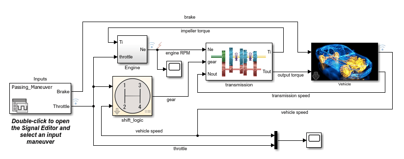
To view the faults, open the Fault Table pane:
Open the Fault Analyzer app. In the Apps tab, click Fault Analyzer.
In the Fault Table pane, expand the
Engine/Outport/1model element.
The model includes these faults:
engineRPM_noise_fault— Adds white noise to the RPM signal when the simulation time is greater than 50 seconds.engineRPM_offset_fault— Adds a constant bias to the engine RPM signal when the simulation time is greater than 50 seconds.
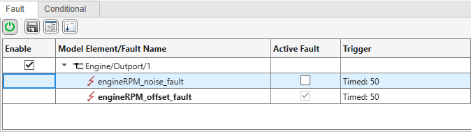
Simulink Fault Analyzer can inject only one fault on a given model element for a simulation. To change the active fault, change the selection in the Active Fault column.
To control when the simulation injects the fault, each fault uses a timed trigger. After injection occurs, Simulink Fault Analyzer adds the fault behavior to the signal. To see the behavior, right-click the fault and click Open fault behavior.
Create the Fault-Embedded Model
To use a model for real-time simulation, you must embed the faults directly into the model.
To create a fault-embedded model, in the Fault Analyzer tab, click Export Embedded Model. For more information on fault embedded models, see Create Fault-Embedded Models.
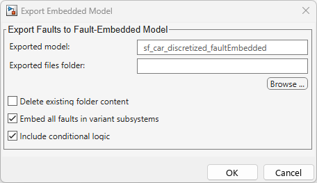
In this example:
Set Exported files folder to an empty folder on the file path.
Clear Delete existing folder content and Include conditional logic.
Select Embed all faults in variant subsystems.
Click OK. Simulink Fault Analyzer saves a new copy of the model in the folder that has embedded faults.
Inspect Fault-Embedded Model
This example includes a copy of the fault-embedded model, sf_car_discretized_faultEmbedded.slx. Open the fault-embedded model:
model = "sf_car_discretized_faultEmbedded";
open_system(model)
In the embedded model, the Engine_Outport1_Fault subsystem models the faults by using a Variant Subsystem block. The Variant Subsystem block uses the fault icon as the mask for the block.
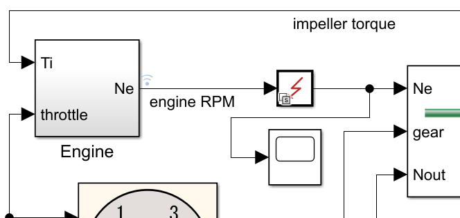
Open the Engine_Outport1_Fault subsystem to view the variant subsystems. The Variant Subsystem block separates the behaviors for each fault into subsystems.
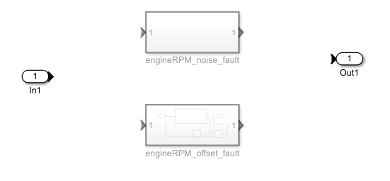
To select an active fault, the variant subsystem uses the variant control variable Engine_Outport1_Fault. When you load the fault-embedded model, Simulink Fault Analyzer defines this variable in the base workspace. These values determine the active fault:
0— No active fault1—engineRPM_noise_faultis active2—engineRPM_offset_faultis active
To adjust the active fault for simulation, change the value of this variable in the MATLAB Command Window, then simulate the model. You can also adjust the values by using the Variant Manager or by changing the block parameters of the Variant Subsystem block.
Generate Real-Time Application from Fault-Embedded Model
To run the model on a Simulink Real-Time target, you must:
Create a Simulink Real-Time system target. For more information, see Target and Application Objects (Simulink Real-Time).
Configure the model to support code generation. See Generate Code from Fault-Embedded Models.
Generate the real-time application.
First, retrieve the target and set the model system target file to the real-time target system target file.
tg = slrealtime;
connect(tg);
modelSTF = getSTFName(tg);
set_param(model,"SystemTargetFile",modelSTF);
Then, configure the model to support code generation. To support code generation in this model, set the solver to a fixed-step solver and disable MAT-file logging.
set_param(model,"SolverType","Fixed-step")
set_param(model,"Solver","ode4")
set_param(model,"MatFileLogging","off")
Finally, generate the real-time application from the model.
evalc("slbuild(model)");Simulink saves the real-time application in the current folder as sf_car_discretized_faultEmbedded.mldatx. This example includes a copy of this executable.
Generate a Dashboard Application
To use the real-time application to control a real-time target, create a dashboard app by using the Simulink Real-Time App Generator. You can design the app to control the fault properties and display model signals. Because the Variant activation time parameter of the Variant Subsystem block is startup, the generated code identifies the active fault before executing the simulation. This setting allows you to choose the active fault before simulating in the app in the real-time environment.
In this example, create an app that controls the injected fault, specifies the fault properties, and displays the engine RPM signal.
Open the Simulink Real-Time App Generator. In the Apps tab, click SLRT App Generator.
Click New and select the real-time application of the fault-embedded model,
sf_car_discretized_faultEmbedded.mldatx.Add the
Engine_Outport1_Faultvariable as a discrete knob. The app sets this variable before the simulation starts, and the model uses its value at startup to select the active fault. Set the values of Knob States toNone,Noise Fault, andOffset Fault, and set their target values to0,1, and2.In the Signals and Parameters pane, expand
sf_car_discretized_faultEmbedded>Engine_Outport1_Fault>engineRPM_noise_fault>FaultBehavior, then add these parameters:In the
engineRPM_noise_faultlist, add theFaultTrigger:Thresholdblock parameter as a numeric edit field.Under
FaultBehavior, add theWhite Noise:MeanandWhite Noise:StdDevblock parameters as numeric edit fields.
In the Signals and Parameters pane, expand
engineRPM_offset_fault>FaultBehavior, then add these parameters:In the
engineRPM_offset_faultlist, add theFaultTrigger:Thresholdblock parameter as a numeric edit field.Under
FaultBehavior, add theOffset_by_1:Biasblock parameter as a numeric edit field.
Click Generate App and save the app. The generated app includes a plot that displays the
engine RPM,throttle, andvehicle speedsignals.
For more information, see Create App Designer Instrument Panels by Using App Generator (Simulink Real-Time). To view this app, open model_fault_app.mlapp. The app opens in App Designer.

Simulate the Model on the Target
To simulate the model from the app:
In the App Designer, click Run. The app opens.
In the app, in the Target Selector property, select the target. To run the model in Simulink without a target, select Simulink Normal Mode.
Click Connect to connect to the target.
Click Load Application to load the real-time application.
Change the knob to specify a fault, and adjust the fault parameters by using the numeric edit fields.
Click Start. The figure plots the engine RPM versus time in real time.
You cannot change the active fault during simulation. To change the fault, change the knob setting and rerun the simulation.
See Also
Simulink.fault.exportEmbeddedModel

