Bluetooth LE Bit Error Rate Simulation with AWGN
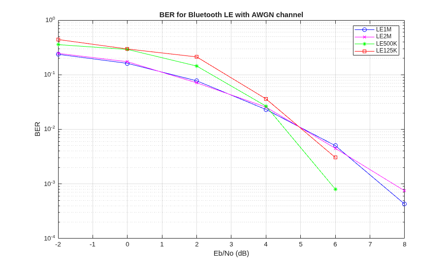
R2026bThis example shows how to measure the bit error rate (BER) for different modes of Bluetooth® low energy (LE) physical layer (PHY) packet types by using the Bluetooth® Toolbox. The PHY packet types are distorted by adding additive white Gaussian noise (AWGN). The simulation results show BER values for each PHY mode.
Introduction
Bluetooth Special Interest Group (SIG) [ 1 ] introduced Bluetooth LE for low-power short-range communications. Bluetooth LE devices operate in the globally unlicensed industrial, scientific, and medical (ISM) band in the frequency range of 2.4 GHz to 2.485 GHz. Bluetooth LE specifies a channel spacing of 2 MHz, which results in 40 radio frequency (RF) channels. The Bluetooth LE standard specifies the link layer (LL) which includes both PHY and MAC layers. Bluetooth LE applications include image and video file transfers between mobile phones, home automation, and the Internet of Things (IoT).
In this example, an end-to-end simulation is used to determine the BER performance of Bluetooth LE under an additive white Gaussian noise (AWGN) channel for a range of bit energy to noise density ratio (Eb/No) values. At each Eb/No point, multiple Bluetooth LE packets are transmitted through a noisy channel with no other radio front-end (RF) impairments. Assuming perfect synchronization, an ideal receiver is used to recover the data bits. These recovered data bits are compared with the transmitted data bits to determine the BER. BER curves are generated for the four PHY transmission throughput modes supported in Bluetooth LE specification [ 2 ] as follows:
Uncoded PHY with data rate of 1 Mbps (LE1M)
Uncoded PHY with data rate of 2 Mbps (LE2M)
Coded PHY with data rate of 500 Kbps (LE500K)
Coded PHY with data rate of 125 Kbps (LE125K)
Link-level Simulation Workflow
This figure shows the link-level simulation. After you generate Bluetooth LE waveforms, these waveforms are distorted with the AWGN. The noisy waveform is then received at the ideal receiver.

Simulations
Configuration
Specify the bit energy to noise power spectral density (Eb/No), samples per symbol, data length, and PHY transmission modes.
EbNo = -2:2:8;              % Eb/No range in dB
sps = 4;                    % Samples per symbol
dataLength = 2080;          % Data length in bits
simMode = ["LE1M","LE2M","LE500K","LE125K"];
These parameters control the number of packets tested at each Eb/No point.
maxNumErrors— This parameter specifies the maximum number of bit errors simulated at each Eb/No point. When the number of bit errors reaches this value, the simulation at this Eb/No is complete.maxNumPackets— This parameter specifies the maximum number of packets simulated at each Eb/No point. When the number of packets reaches this value, the simulation at this Eb/No is complete.
Specify the maxNumErrors and maxNumPackets values. For the purpose of this example, specify small values for maxNumErrors and maxNumPackets. For statistically meaningful results, you can simulate the example with higher maxNumErrors and maxNumPackets values.
maxNumErrors = 1e2;         % Maximum number of bit errors at an Eb/No point
maxNumPackets = 10;         % Maximum number of packets at an Eb/No point
Get the number of PHY modes for simulation.
numMode = numel(simMode); % Number of modes
Calculate the number of Eb/No points of simulation.
snrLength = length(EbNo);
Preallocate the space to store the BER results.
ber = zeros(numMode,snrLength); % Pre-allocate to store BER results
Simulating for each PHY mode
This example demonstrates how to speed up the simulation by using a parfor loop, instead of a for loop simulate each Eb/No point. The parfor loop reduces the total simulation time by executing the processing for each PHY mode simultaneously. To utilize the parfor loop, you need the Parallel Computing Toolbox, license. By commenting out the for statement, you can enable the use of parallel computing and enhance simulation speed. If you do not install the Parallel Computing Toolbox , by default, the example uses the for loop causing the simulation to run on a single core.
% parfor countMode = 1:numMode
for countMode = 1:numMode

    % For each PHY mode, set the signal-to-noise ratio (SNR). For coded
    % PHYs (LE500K and LE125K), the SNR calculation includes the 1/2 and
    % 1/8 code rate respectively.

    phyMode = simMode(countMode);

    if any(phyMode==["LE1M","LE2M"])
        snrVec = EbNo - 10*log10(sps);
    else
        if phyMode == "LE500K"
            codeRate = 1/2;
        else
            codeRate = 1/8;
        end
        snrVec = EbNo + 10*log10(codeRate) - 10*log10(sps);
    end

    % *Simulate for Each Eb/No Point*
    for countSnr = 1:snrLength

        % To ensure that each iteration uses a repeatable set of random
        % numbers, set a random substream index for each iteration.
        stream = RandStream("combRecursive",Seed=0);
        stream.Substream = countSnr;
        RandStream.setGlobalStream(stream);

        % Create an instance of error rate.
        errorRate = comm.ErrorRate(Samples="Custom", ...
            CustomSamples=1:dataLength);

        % Initialize the parameters for error computation. The numErrors is
        % used for accumulating errors while the numPacket is used for
        % number of packets received successfully.
        numErrors = 0;
        numPacket = 1;

        while numErrors < maxNumErrors && numPacket < maxNumPackets

            % Configure and generate the Bluetooth LE waveform by providing
            % the data bits, the PHY transmission mode, the samples per
            % symbol value, the channel index, and the access address.
            txBits = randi([0 1],dataLength,1,"int8");  % Data bits generation
            channelIndex = randi([0 39],1,1);           % Random channel index value for each packet
            if channelIndex <= 36
                % Random access address for data channels Ideally, this
                % access address value should meet the requirements
                % specified in Section 2.1.2, Part-B, Vol-6 of Bluetooth
                % specification.
                accessAddress = [1 0 0 0 1 1 1 0 1 1 0 0 1 0 0 1 1 0 1 ...
                    1 1 1 1 0 1 1 0 1 0 1 1 0]';
            else
                % Default access address for periodic advertising channels
                accessAddress = [0 1 1 0 1 0 1 1 0 1 1 1 1 1 0 1 1 0 0 ...
                    1 0 0 0 1 0 1 1 1 0 0 0 1]';
            end
            txWaveform = bleWaveformGenerator(txBits,Mode=phyMode, ...
                SamplesPerSymbol=sps, ...
                ChannelIndex=channelIndex, ...
                AccessAddress=accessAddress);

            % Add AWGN to the generated waveform.
            [rxWaveform,nVar] = awgn(txWaveform,snrVec(countSnr),"measured");

            % Recover data bits from the noisy waveform by using the ideal
            % receiver. The ideal receiver assumes that the noisy signal is
            % in perfect synchronization with respect to time, frequency
            % and phase.
            rxBits = bleIdealReceiver(rxWaveform, ...
                Mode=phyMode, ...
                SamplesPerSymbol=sps, ...
                ChannelIndex=channelIndex);

            % Determine the BER by comparing transmitted and received bits.
            if(length(txBits) == length(rxBits))
                errors = errorRate(txBits,rxBits);      % Accumulate error
                ber(countMode,countSnr) = errors(1);    % Accumulated BER
                currentErrors = errors(2)-numErrors;    % Number of errors in current packet
                numErrors = errors(2);                  % Accumulated errors
            end
            numPacket = numPacket + 1;                  % Increment the packet number
        end

        % Display message for the particular value of SNR
        disp("Mode "+phyMode+",Eb/No = "+num2str(EbNo(countSnr))+"dB,"+ ...
            " BER is: "+num2str(ber(countMode,countSnr)));
    end
end
Mode LE1M,Eb/No = -2dB, BER is: 0.23654
Mode LE1M,Eb/No = 0dB, BER is: 0.16154
Mode LE1M,Eb/No = 2dB, BER is: 0.077404
Mode LE1M,Eb/No = 4dB, BER is: 0.023077
Mode LE1M,Eb/No = 6dB, BER is: 0.0050214
Mode LE1M,Eb/No = 8dB, BER is: 0.00042735
Mode LE2M,Eb/No = -2dB, BER is: 0.24615
Mode LE2M,Eb/No = 0dB, BER is: 0.17308
Mode LE2M,Eb/No = 2dB, BER is: 0.071154
Mode LE2M,Eb/No = 4dB, BER is: 0.025481
Mode LE2M,Eb/No = 6dB, BER is: 0.0044872
Mode LE2M,Eb/No = 8dB, BER is: 0.00074786
Mode LE500K,Eb/No = -2dB, BER is: 0.35577
Mode LE500K,Eb/No = 0dB, BER is: 0.29087
Mode LE500K,Eb/No = 2dB, BER is: 0.14423
Mode LE500K,Eb/No = 4dB, BER is: 0.026603
Mode LE500K,Eb/No = 6dB, BER is: 0.00080128
Mode LE500K,Eb/No = 8dB, BER is: 0
Mode LE125K,Eb/No = -2dB, BER is: 0.44135
Mode LE125K,Eb/No = 0dB, BER is: 0.29615
Mode LE125K,Eb/No = 2dB, BER is: 0.21202
Mode LE125K,Eb/No = 4dB, BER is: 0.036058
Mode LE125K,Eb/No = 6dB, BER is: 0.0030449
Mode LE125K,Eb/No = 8dB, BER is: 0
Results and Visualizations
Specify the marker, color, and space for the legend variable.
marker = "ox*s";
color = "bmgr";
legendVar = strings(numMode,1);
Plot the BER curve for each PHY modes.
for countMode = 1:numMode
    semilogy(EbNo,ber(countMode,:).',"-"+marker{1}(countMode)+color{1}(countMode))
    hold on
    legendVar(countMode) = simMode(countMode);
end
grid on
xlabel("Eb/No (dB)")
ylabel("BER")
legend(legendVar)
title("BER for Bluetooth LE with AWGN channel")
hold off
Further Exploration
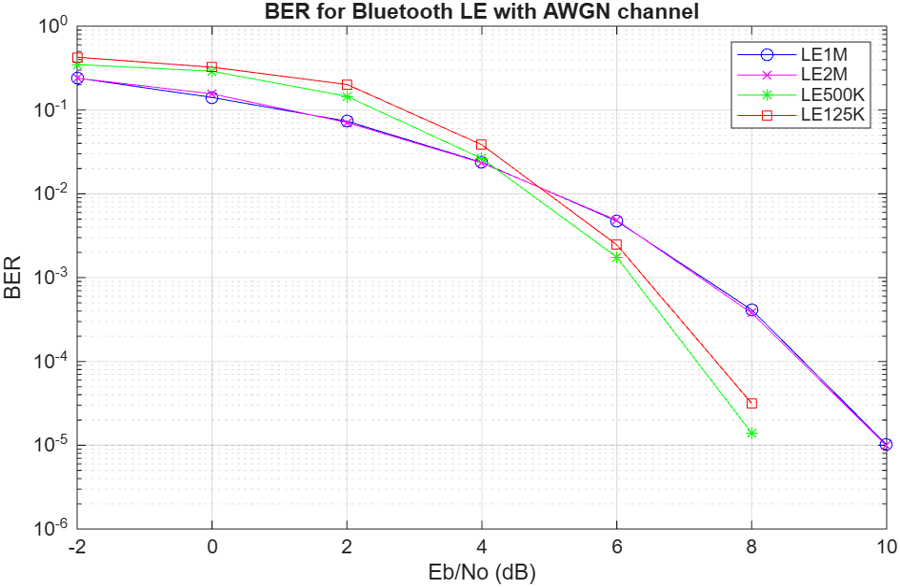
You can further explore this example by increasing the maxNumErrors and maxNumPackets parameters. This BER result is obtained by using this configuration.
dataLength— 2000 bitsmaxNumErrors— 1000maxNumPackets— 10000
This example simulates a Bluetooth LE physical layer link over an AWGN channel. It shows how to generate Bluetooth LE waveforms, demodulate and decode bits using an ideal receiver and compute the BER.
Selected Bibliography
Bluetooth Technology Website. "Bluetooth Technology Website | The Official Website of Bluetooth Technology." Accessed January 22, 2026. https://www.bluetooth.com.
Bluetooth Core Specifications Working Group. "Bluetooth Core Specification" v6.1. https://www.bluetooth.com/specifications/specs/core-specification-6-1/.

